Infiniti EX35. Manual - part 640


  Index      Infiniti     Infiniti EX35 - service repair manual 2008 year


Search            


Content   ..  638  639  640  641   ..


Infiniti EX35. Manual - part 640


EC-302

< COMPONENT DIAGNOSIS >

[VQ35HR]

P0453 EVAP CONTROL SYSTEM PRESSURE SENSOR

P0453 EVAP CONTROL SYSTEM PRESSURE SENSOR

Description

INFOID:0000000003133452

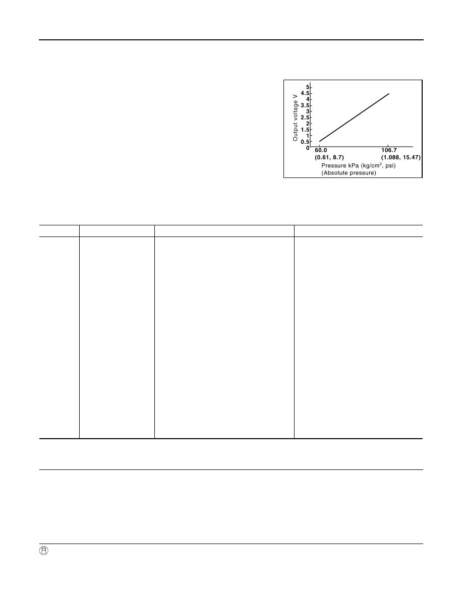
The EVAP control system pressure sensor detects pressure in the
purge line. The sensor output voltage to the ECM increases as pres-
sure increases.

DTC Logic

INFOID:0000000003133453

DTC DETECTION LOGIC

DTC CONFIRMATION PROCEDURE

1.

PRECONDITIONING

If DTC Confirmation Procedure has been previously conducted, always turn ignition switch OFF and wait at
least 10 seconds before conducting the next test.
TESTING CONDITION:
Always perform test at a temperature of 5

°

C (41

°

F) or more.

>> GO TO 2.

2.

PERFORM DTC CONFIRMATION PROCEDURE

With CONSULT-III

1.

Start engine and warm it up to normal operating temperature.

2.

Turn ignition switch OFF and wait at least 10 seconds.

PBIB3370E

DTC No.

Trouble diagnosis name

DTC detecting condition

Possible cause

P0453

EVAP control system 
pressure sensor high in-
put

An excessively high voltage from the sensor is 
sent to ECM.

• Harness or connectors

(EVAP control system pressure sensor 
circuit is open or shorted.)
[CKP sensor (POS) circuit is shorted.]
[CMP sensor (PHASE) (bank 2) circuit is 
shorted.]
[EVT control position sensor (bank 2) cir-
cuit is shorted.]
(Battery current sensor circuit is shorted.)
(APP sensor 2 circuit is shorted.)
(Refrigerant pressure sensor circuit is 
shorted.)

• EVAP control system pressure sensor
• Crankshaft position sensor (POS)
• Camshaft position sensor (PHASE) 

(bank 2)

• Exhaust valve timing control position sen-

sor (bank 2)

• Battery current sensor
• Accelerator pedal position sensor
• Refrigerant pressure sensor
• EVAP canister vent control valve
• EVAP canister
• Rubber hose from EVAP canister vent 

control valve to vehicle frame

P0453 EVAP CONTROL SYSTEM PRESSURE SENSOR

EC-303

< COMPONENT DIAGNOSIS >

[VQ35HR]

C

D

E

F

G

H

I

J

K

L

M

A

EC

N

P

O

3.

Turn ignition switch ON.

4.

Select “DATA MONITOR” mode with CONSULT-III.

5.

Check that “FUEL T/TMP SE” is more than 0

°

C (32

°

F).

6.

Start engine and wait at least 20 seconds.

7.

Check 1st trip DTC.

With GST

1.

Start engine and warm it up to normal operating temperature.

2.

Set voltmeter probes to ECM harness connector terminals under the following conditions.

3.

Check that the voltage is less than 4.2 V.

4.

Turn ignition switch OFF and wait at least 10 seconds.

5.

Start engine and wait at least 20 seconds.

6.

Check 1st trip DTC.

Is 1st trip DTC detected?

YES

>> Go to 

EC-303, "Diagnosis Procedure"

.

NO

>> INSPECTION END

Diagnosis Procedure

INFOID:0000000003133454

1.

CHECK GROUND CONNECTION

1.

Turn ignition switch OFF.

2.

Check ground connection M95. Refer to Ground Inspection in 

GI-41, "Circuit Inspection"

.

Is the inspection result normal?

YES

>> GO TO 2.

NO

>> Repair or replace ground connection.

2.

CHECK CONNECTOR

1.

Disconnect EVAP control system pressure sensor harness connector.

2.

Check sensor harness connector for water.

Is the inspection result normal?

YES

>> GO TO 3.

NO

>> Repair or replace harness connector.

3.

CHECK EVAP CONTROL SYSTEM PRESSURE SENSOR POWER SUPPLY CIRCUIT

1.

Turn ignition switch ON.

2.

Check the voltage between EVAP control system pressure sensor harness connector and ground.

Is the inspection result normal?

YES

>> GO TO 10.

NO

>> GO TO 4.

4.

CHECK EVAP CONTROL SYSTEM PRESSURE SENSOR POWER SUPPLY CIRCUIT-II

1.

Turn ignition switch OFF.

2.

Disconnect ECM harness connector.

ECM

Ground

Connector

+

Terminal

Terminal

M107

106

(Fuel tank temperature sensor signal)

128

Water should not exist.

EVAP control system pressure sensor

Ground

Voltage (V)

Connector

Terminal

B252

3

Ground

Approx. 5

EC-304

< COMPONENT DIAGNOSIS >

[VQ35HR]

P0453 EVAP CONTROL SYSTEM PRESSURE SENSOR

3.

Check the continuity between EVAP control system pressure sensor harness connector and ECM har-
ness connector.

Is the inspection result normal?

YES

>> GO TO 6.

NO

>> GO TO 5.

5.

DETECT MALFUNCTIONING PART

Check the following.
• Harness connectors B201, M117
• Harness for open between ECM and EVAP control system pressure sensor

>> Repair open circuit.

6.

CHECK SENSOR POWER SUPPLY CIRCUIT

Check harness for short to power and short to ground, between the following terminals.

Is the inspection result normal?

YES

>> GO TO 7.

NO

>> Repair short to ground or short to power in harness or connectors. 

7.

CHECK COMPONENTS

Check the following.
• Crankshaft position sensor (POS) (Refer to 

EC-255, "Component Inspection"

.)

• Camshaft position sensor (PHASE) (bank 2) (Refer to 

EC-260, "Component Inspection"

.)

• Exhaust valve timing control position sensor (bank 2) (Refer to 

EC-348, "Component Inspection"

.)

• Battery current sensor (Refer to 

EC-379, "Component Inspection"

.)

• Refrigerant pressure sensor (Refer to 

HAC-88, "Diagnosis Procedure"

.)

Is the inspection result normal?

YES

>> GO TO 8.

NO

>> Replace malfunctioning component.

8.

CHECK APP SENSOR

Refer to 

EC-423, "Component Inspection"

.

Is the inspection result normal?

YES

>> GO TO 20.

NO

>> GO TO 9.

9.

REPLACE ACCELERATOR PEDAL ASSEMBLY

1.

Replace accelerator pedal assembly

2.

Go to 

EC-423, "Special Repair Requirement"

.

EVAP control system pressure sensor

ECM

Continuity

Connector

Terminal

Connector

Terminal

B252

3

M107

107

Existed

ECM

Sensor

Connector

Terminal

Name

Connector

Terminal

F101

46

CKP sensor (POS)

F2

1

F102

64

CMP sensor (PHASE) (bank 2)

F18

1

EVT control position sensor (bank 2)

F19

1

Battery current sensor

E21

1

M107

103

APP sensor

E112

6

107

EVAP control system pressure sensor

B252

3

111

Refrigerant pressure sensor

E77

3

P0453 EVAP CONTROL SYSTEM PRESSURE SENSOR

EC-305

< COMPONENT DIAGNOSIS >

[VQ35HR]

C

D

E

F

G

H

I

J

K

L

M

A

EC

N

P

O

>> INSPECTION END

10.

CHECK EVAP CONTROL SYSTEM PRESSURE SENSOR GROUND CIRCUIT FOR OPEN AND

SHORT

1.

Turn ignition switch OFF.

2.

Disconnect ECM harness connector.

3.

Check the continuity between EVAP control system pressure sensor harness connector and ECM har-
ness connector.

4.

Also check harness for short to ground and short to power.

Is the inspection result normal?

YES

>> GO TO 12.

NO

>> GO TO 11.

11.

DETECT MALFUNCTIONING PART

Check the following.
• Harness connectors B201, M117
• Harness for open or short between EVAP control system pressure sensor and ECM

>> Repair open circuit or short to ground or short to power in harness or connectors.

12.

CHECK EVAP CONTROL SYSTEM PRESSURE SENSOR INPUT SIGNAL CIRCUIT FOR OPEN AND

SHORT

1.

Check the continuity between EVAP control system pressure sensor harness connector and ECM har-
ness connector.

2.

Also check harness for short to ground and short to power.

Is the inspection result normal?

YES

>> GO TO 14.

NO

>> GO TO 13.

13.

DETECT MALFUNCTIONING PART

Check the following.
• Harness connectors B201, M117
• Harness for open or short between EVAP control system pressure sensor and ECM

>> Repair open circuit or short to ground or short to power in harness or connectors.

14.

CHECK RUBBER TUBE

1.

Disconnect rubber tube connected to EVAP canister vent control valve.

2.

Check the rubber tube for clogging.

Is the inspection result normal?

YES

>> GO TO 15.

NO

>> Clean the rubber tube using an air blower, repair or replace rubber tube.

15.

CHECK EVAP CANISTER VENT CONTROL VALVE

Refer to 

EC-288, "Component Inspection"

.

Is the inspection result normal?

YES

>> GO TO 16.

EVAP control system pressure sensor

ECM

Continuity

Connector

Terminal

Connector

Terminal

B252

1

M107

112

Existed

EVAP control system pressure sensor

ECM

Continuity

Connector

Terminal

Connector

Terminal

B252

2

M107

102

Existed


Content   ..  638  639  640  641   ..