Infiniti EX35. Manual - part 576
EC-46
< FUNCTION DIAGNOSIS >
[VQ35HR]
ELECTRIC IGNITION SYSTEM
4.
EVAP canister vent control valve
5.
EVAP control system pressure sen-
sor
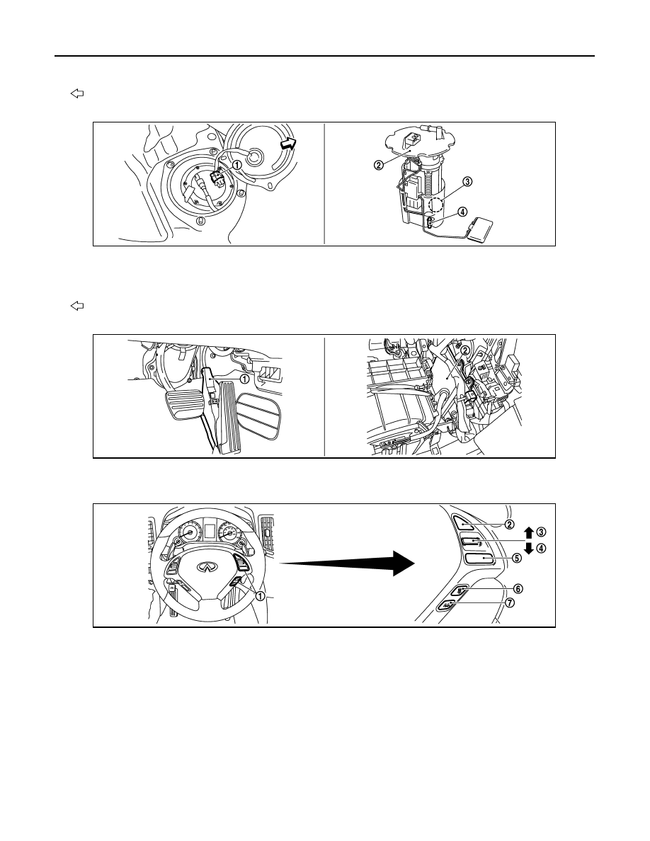
: Vehicle front
1.
Fuel level sensor unit and fuel pump
harness connector
2.
Fuel level sensor unit and fuel pump 3.
Fuel pressure regulator
4.
Fuel tank temperature sensor
: Vehicle front
1.
Accelerator pedal position sensor
2.
ECM
1.
ICC steering switch
2.
CANCEL switch
3.
RESUME/ACCELERATE switch
4.
SET/COAST switch
5.
MAIN switch
6.
DISTANCE switch
7.
LDP switch
JMBIA1182ZZ
JMBIA0015ZZ
JMBIA1308ZZ