Infiniti EX35. Manual - part 533
DLN-82
< ON-VEHICLE REPAIR >
[REAR PROPELLER SHAFT: 3S80A-R]
REAR PROPELLER SHAFT
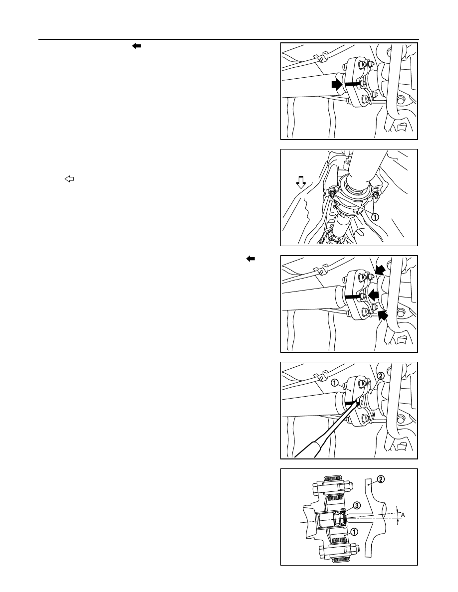
5.
Put matching marks (
) onto propeller shaft rubber coupling
and final drive companion flange.
CAUTION:
For matching marks, use paint. Never damage propeller
shaft rubber coupling and final drive companion flange.
6.
Loosen mounting nuts (1) of center bearing mounting brackets
(upper/lower).
CAUTION:
Tighten mounting nuts temporarily.
7.
Remove propeller shaft assembly fixing bolts and nuts (
).
CAUTION:
Never remove the rubber coupling from the propeller shaft
assembly.
8.
Slightly separate the rubber coupling (1) from the final drive
companion flange (2).
CAUTION:
Never damage the final drive companion flange and rubber
coupling.
9.
Remove center bearing mounting bracket fixing nuts.
CAUTION:
• The angle (A), which the third axis rubber coupling (1)
forms with the final drive companion flange (2), must be 5
°
or less.
• Never damage the grease seal (3).
• Never damage the rubber coupling.
10. Slide the propeller shaft in the vehicle forward direction slightly.
Separate the propeller shaft from the final drive companion
flange.
CAUTION:
JSDIA0009ZZ
: Vehicle front
JPDID0187ZZ
JSDIA0010ZZ
JSDIA0128ZZ
JSDIA0137ZZ