Infiniti EX35. Manual - part 508


  Index      Infiniti     Infiniti EX35 - service repair manual 2008 year


Search            


Content   ..  506  507  508  509   ..


Infiniti EX35. Manual - part 508


DLK-246

< ON-VEHICLE REPAIR >

[INTELLIGENT KEY SYSTEM]

FRONT DOOR LOCK

10. While pulling outside handle bracket, slide toward rear of vehicle

to remove outside handle bracket.

11. Reach in to separate outside handle cable connection on outside handle bracket.

12. Remove door lock assembly TORX bolts.

13. Disconnect door lock actuator connector, and then remove door lock assembly.
14. Remove key rod from door lock assembly.

INSTALLATION

Install in the reverse order of removal.

CAUTION:

• When installing each rod, rotate rod holder until a click is felt.
• Check door open/close, lock/unlock operation after installation. 

INSIDE HANDLE

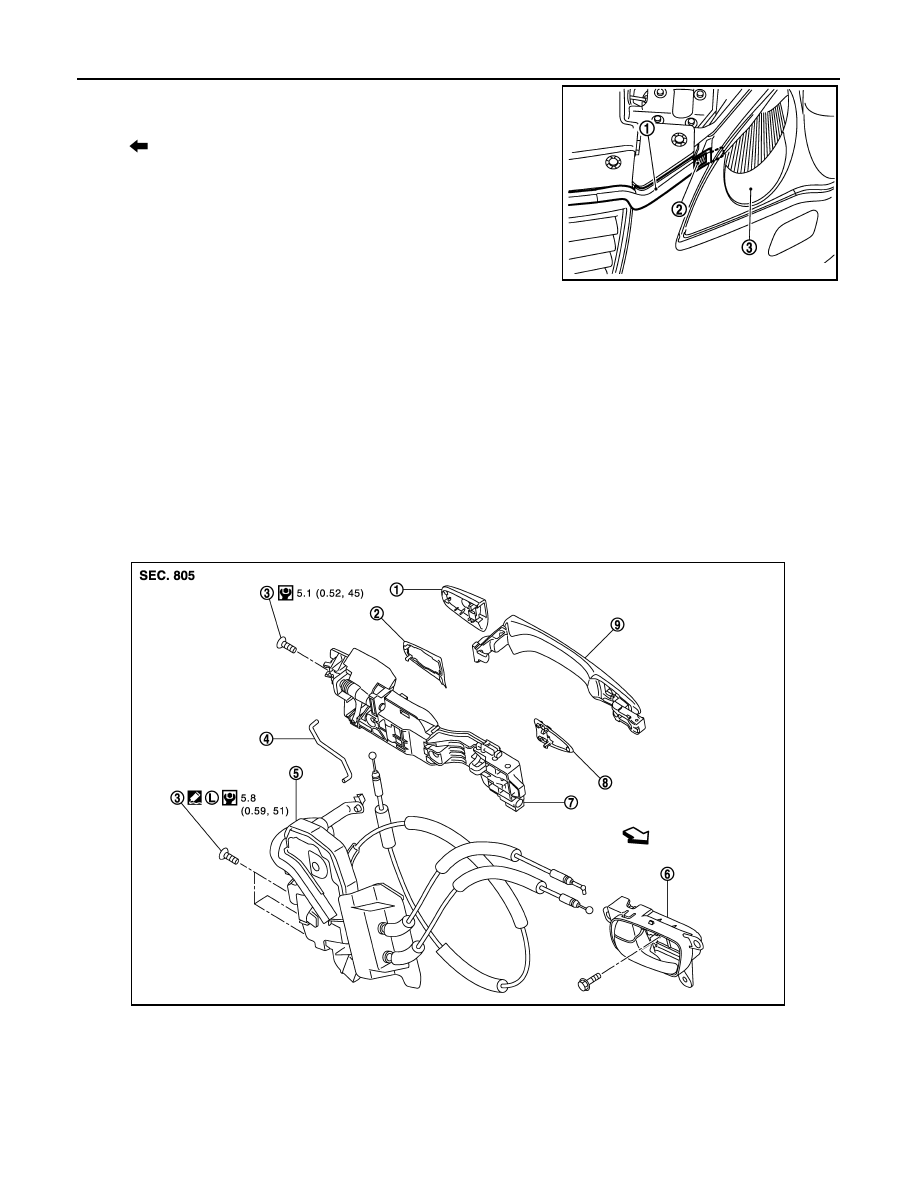
INSIDE HANDLE : Exploded View

INFOID:0000000003691280

: Pawl

JMKIA2302ZZ

1.

Door key cylinder assembly (driver 
side)
Outside handle escutcheon (passen-
ger side)

2.

Rear gasket

3.

TORX bolt

4.

Key rod (driver side)

5.

Door lock assembly

6.

Inside handle

7.

Outside handle bracket

8.

Front gasket

9.

Outside handle

JMKIA2053GB

FRONT DOOR LOCK

DLK-247

< ON-VEHICLE REPAIR >

[INTELLIGENT KEY SYSTEM]

C

D

E

F

G

H

I

J

L

M

A

B

DLK

N

O

P

INSIDE HANDLE : Removal and Installation

INFOID:0000000003556367

REMOVAL

1.

Remove front door finisher. Refer to 

INT-11, "DRIVER SIDE : Removal and Installation"

 (driver side) or

INT-14, "PASSENGER SIDE : Removal and Installation"

 (passenger side).

2.

Disconnect inside handle cable, and then remove the inside handle.

3.

Remove inside handle mounting screws.

INSTALLATION

Install in the reverse order of removal.

CAUTION:

Check door open/close, lock/unlock operation after installation.

OUTSIDE HANDLE

OUTSIDE HANDLE : Exploded View

INFOID:0000000003691281

OUTSIDE HANDLE : Removal and Installation

INFOID:0000000003556369

REMOVAL

: Vehicle front

Refer to 

GI-4, "Components"

 for symbols in the figure.

1.

Door key cylinder assembly (driver 
side)
Outside handle escutcheon (passen-
ger side)

2.

Rear gasket

3.

TORX bolt

4.

Key rod (driver side)

5.

Door lock assembly

6.

Inside handle

7.

Outside handle bracket

8.

Front gasket

9.

Outside handle

: Vehicle front

Refer to 

GI-4, "Components"

 for symbols in the figure.

JMKIA2053GB

DLK-248

< ON-VEHICLE REPAIR >

[INTELLIGENT KEY SYSTEM]

FRONT DOOR LOCK

1.

Remove front door finisher. Refer to 

INT-11, "DRIVER SIDE : Removal and Installation"

 (driver side) or

INT-14, "PASSENGER SIDE : Removal and Installation"

 (passenger side).

2.

Remove front door glass. Refer to 

GW-17, "Removal and Installation"

.

3.

Remove front door module assembly. Refer to 

GW-20, "Removal and Installation"

.

4.

Disconnect door antenna and door request switch connector and remove harness clamp (models with
Intelligent Key system) on outside handle bracket.

5.

Remove door side grommet, and loosen TORX bolt from grom-
met hole.

CAUTION:

Never remove TORX bolt forcibly.

6.

Reach in to separate key rod (2) connection [on the door key
cylinder assembly (1)] (driver side).

7.

While pulling outside handle, remove door key cylinder assem-
bly (driver side) or outside handle escutcheon (passenger side).

8.

While pulling outside handle (1), slide toward rear of vehicle to
remove outside handle.

9.

Remove front gasket and rear gasket.

: TORX bolt

JMKIA2094ZZ

JMKIA0553ZZ

JMKIA0560ZZ

JMKIA0524ZZ

FRONT DOOR LOCK

DLK-249

< ON-VEHICLE REPAIR >

[INTELLIGENT KEY SYSTEM]

C

D

E

F

G

H

I

J

L

M

A

B

DLK

N

O

P

10. While pulling outside handle bracket, slide toward rear of vehicle

to remove outside handle bracket.

11. Reach in to separate outside handle cable connection on outside handle bracket.

INSTALLATION

Install in the reverse order of removal.

CAUTION:

• When installing each rod, rotate rod holder until a click is felt.
• Check door open/close, lock/unlock operation after installation.

: Pawl

JMKIA2302ZZ


Content   ..  506  507  508  509   ..