Infiniti EX35. Manual - part 505
DLK-234
< ON-VEHICLE REPAIR >
[INTELLIGENT KEY SYSTEM]
BACK DOOR
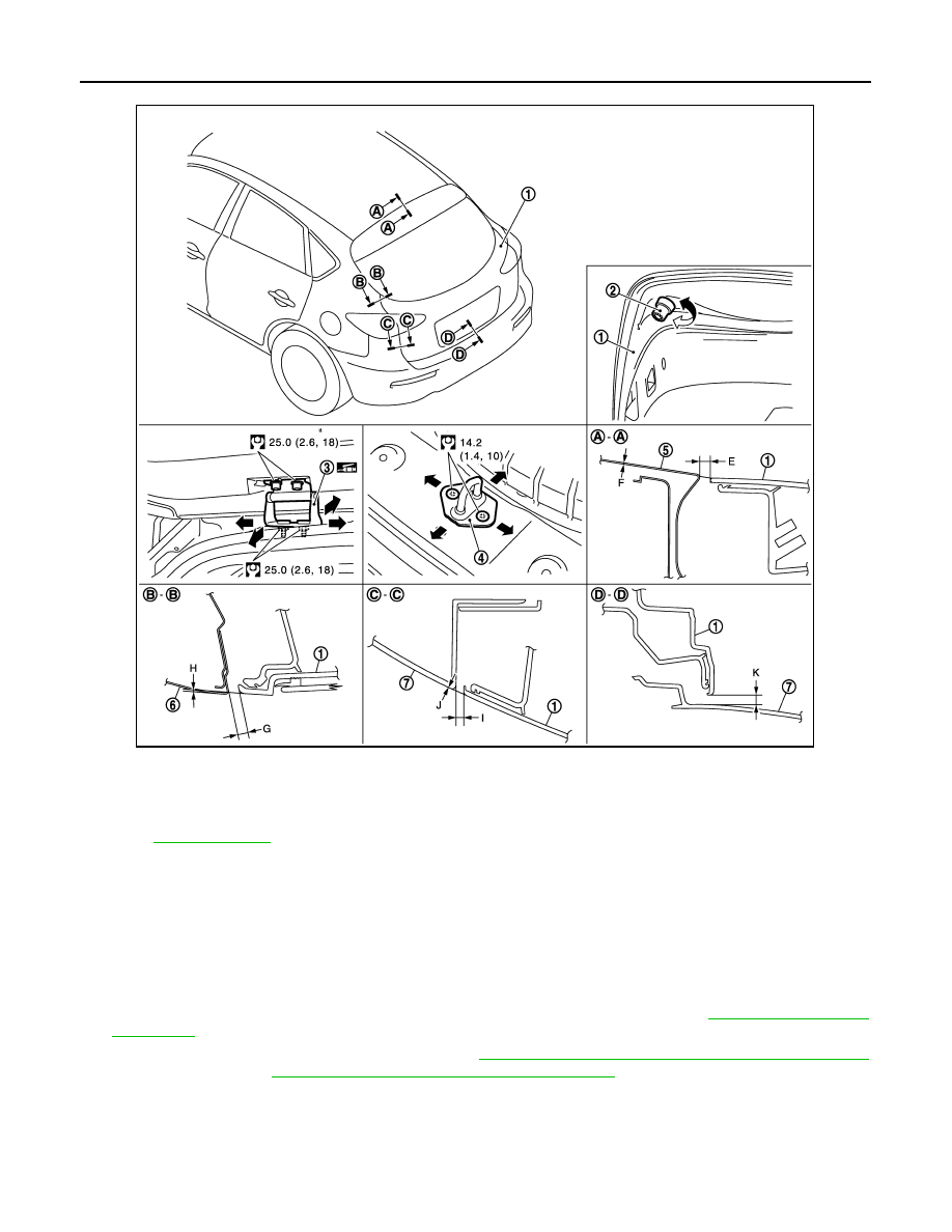
BACK DOOR ASSEMBLY : Removal and Installation
INFOID:0000000003556354
CAUTION:
Operate with two workers, because of its heavy weight.
NOTE:
The back door harness constitute the back door assembly.
REMOVAL
1.
Remove back door finisher inner, back door plate, back door hinge cover. Refer to
.
2.
Remove clips of head lining at rear end. Refer to
INT-27, "NORMAL ROOF : Removal and Installation"
(NORMAL ROOF) or
INT-30, "SUNROOF : Removal and Installation"
(SUNROOF).
1.
Back door assembly
2.
Bumper rubber
3.
Back door hinge
4.
Back door striker
5.
Roof
6.
Body side outer
7.
Rear bumper fascia
Refer to
for symbols in the figure.
JMKIA2088GB