Infiniti EX35. Manual - part 358


  Index      Infiniti     Infiniti EX35 - service repair manual 2008 year


Search            


Content   ..  356  357  358  359   ..


Infiniti EX35. Manual - part 358


BRM-34

< REMOVAL AND INSTALLATION >

REPAIRING HIGH STRENGTH STEEL

REPAIRING HIGH STRENGTH STEEL

High Strength Steel (HSS)

INFOID:0000000003134503

High strength steel is used for body panels in order to reduce vehicle weight.
Accordingly, precautions in repairing automotive bodies made of high strength steel are described below:

Read the following precautions when repairing HSS:

1.

Additional points to consider
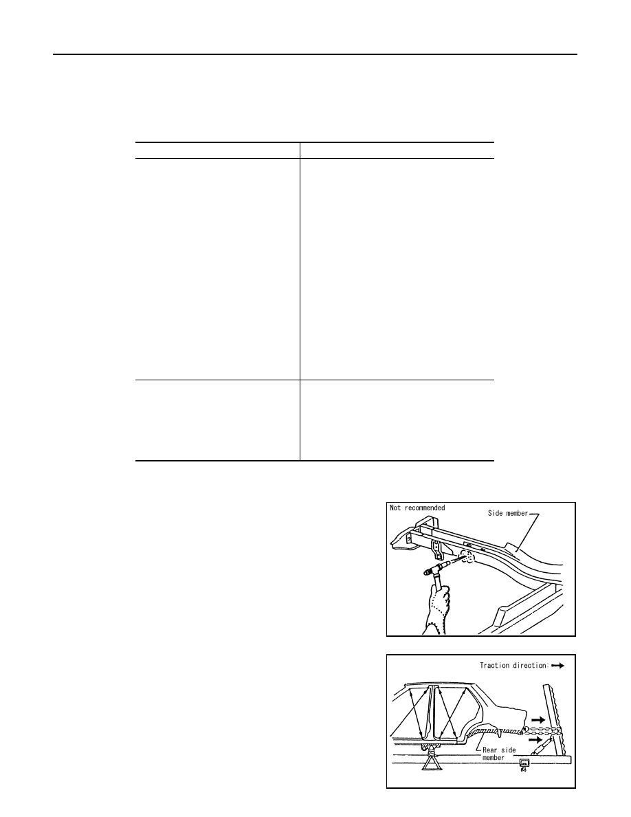
• The repair of reinforcements (such as side members) by heat-

ing is not recommended since it may weaken the component.
When heating is unavoidable, do not heat HSS parts above
550

°

C (1,022

°

F).

Verify heating temperature with a thermometer.
(Crayon-type and other similar type thermometer are appropri-
ate.)

• When straightening body panels, use caution in pulling any

HSS panel. Because HSS is very strong, pulling may cause
deformation in adjacent portions of the body. In this case,
increase the number of measuring points, and carefully pull
the HSS panel.

Tensile strength

Major applicable parts

370 - 590 MPa

• Front strut housing
• Hoodledge reinforcement
• Upper front hoodledge
• Lower dash
• Lower dash crossmember assembly
• Front roof rail
• Upper inner front pillar assembly
• Inner center pillar
• Inner sill
• Upper & lower outer rear wheelhouse exten-

sion

• Center front floor
• Front  floor

(Component part) 

• Front & rear side member assembly 
• Front side member closing plate assembly 
• Front side member outrigger assembly
• Front side member rear extension
• Rear seat crossmember
• Other reinforcements

780 - 1350 MPa

• Center pillar reinforcement

(Component part) 

• Inner center pillar

(Component part) 

• Outer side roof rail reinforcement
• Outer sill reinforcement

(Component part) 

PIIA0115E

PIIA0116E

REPAIRING HIGH STRENGTH STEEL

BRM-35

< REMOVAL AND INSTALLATION >

C

D

E

F

G

H

I

J

L

M

A

B

BRM

N

O

P

• When cutting HSS panels, avoid gas (torch) cutting if possible.

Instead, use a saw to avoid weakening surrounding areas due
to heat. If gas (torch) cutting is unavoidable, allow a minimum
margin of 50 mm (1.97in).

• When welding HSS panels, use spot welding whenever possi-

ble in order to minimize weakening surrounding areas due to
heat.
If spot welding is impossible, use MIG. welding. Do not use
gas (torch) for welding because it is inferior in welding
strength.

• The spot weld on HSS panels is harder than that of an ordi-

nary steel panel.
Therefore, when cutting spot welds on a HSS panel, use a low
speed high torque drill (1,000 to 1,200 rpm) to increase drill bit
durability and facilitate the operation.

2.

Precautions in spot welding HSS
This work should be performed under standard working condi-
tions. Always note the following when spot welding HSS:
• The electrode tip diameter must be sized properly according to

the metal thickness.

PIIA0117E

PIIA0144E

PIIA0145E

PIIA0146E

BRM-36

< REMOVAL AND INSTALLATION >

REPAIRING HIGH STRENGTH STEEL

• The panel surfaces must fit flush to each other, leaving no

gaps.

• Follow the specifications for the proper welding pitch.

Unit: mm (in)

PIIA0147E

Thickness (t)

Minimum pitch (l)

0.6 (0.024)
0.8 (0.031)
1.0 (0.039)
1.2 (0.047)
1.6 (0.063)
1.8 (0.071)

10 (0.39) or over
12 (0.47) or over
18 (0.71) or over
20 (0.79) or over
27 (1.06) or over
31 (1.22) or over

PIIA0148E

REPLACEMENT OPERATIONS

BRM-37

< REMOVAL AND INSTALLATION >

C

D

E

F

G

H

I

J

L

M

A

B

BRM

N

O

P

REPLACEMENT OPERATIONS

Description

INFOID:0000000003757467

• This section is prepared for technicians who have attained a high level of skill and experience in repairing

collision-damaged vehicles and also use modern service tools and equipment. Persons unfamiliar with body
repair techniques should not attempt to repair collision-damaged vehicles by using this section.

• Technicians are also encouraged to read Body Repair Manual (Fundamentals) in order to ensure that the

original functions and quality of the vehicle can be maintained. The Body Repair Manual (Fundamentals)
contains additional information, including cautions and warning, that are not including in this manual. Techni-
cians should refer to both manuals to ensure proper repairs.

• Please note that these information are prepared for worldwide usage, and as such, certain procedures might

not apply in some regions or countries.

The symbols used in this section for welding operations are shown below.

Symbol marks

Description

2-spot welds

3-spot welds

MIG plug weld

For 3 panels plug weld method

MIG seam weld / Point weld

JSKIA0049ZZ

JSKIA0053ZZ

JSKIA0050ZZ

JSKIA0051ZZ

JSKIA0054ZZ

JSKIA0055ZZ

JSKIA0052ZZ

JSKIA0056ZZ


Content   ..  356  357  358  359   ..