Infiniti EX35. Manual - part 282
AV
CENTER SPEAKER
AV-909
< ON-VEHICLE REPAIR >
[BOSE AUDIO WITH NAVIGATION]
C
D
E
F
G
H
I
J
K
L
M
B
A
O
P
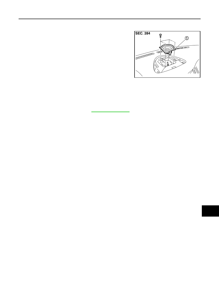
CENTER SPEAKER
Exploded View
INFOID:0000000003160776
Removal and Installation
INFOID:0000000003160777
REMOVAL
1.
Remove center speaker grille. Refer to
2.
Remove center speaker mounting screws, lift up the center speaker and disconnect center speaker con-
nector.
3.
Remove center speaker.
INSTALLATION
Installation is the reverse order of removal.
JPNIA0886ZZ
1.
Center speaker