Infiniti EX35. Manual - part 278


  Index      Infiniti     Infiniti EX35 - service repair manual 2008 year


Search            


Content   ..  276  277  278  279   ..


Infiniti EX35. Manual - part 278


AV

MULTI AV SYSTEM SYMPTOMS

AV-893

< SYMPTOM DIAGNOSIS >

[BOSE AUDIO WITH NAVIGATION]

C

D

E

F

G

H

I

J

K

L

M

B

A

O

P

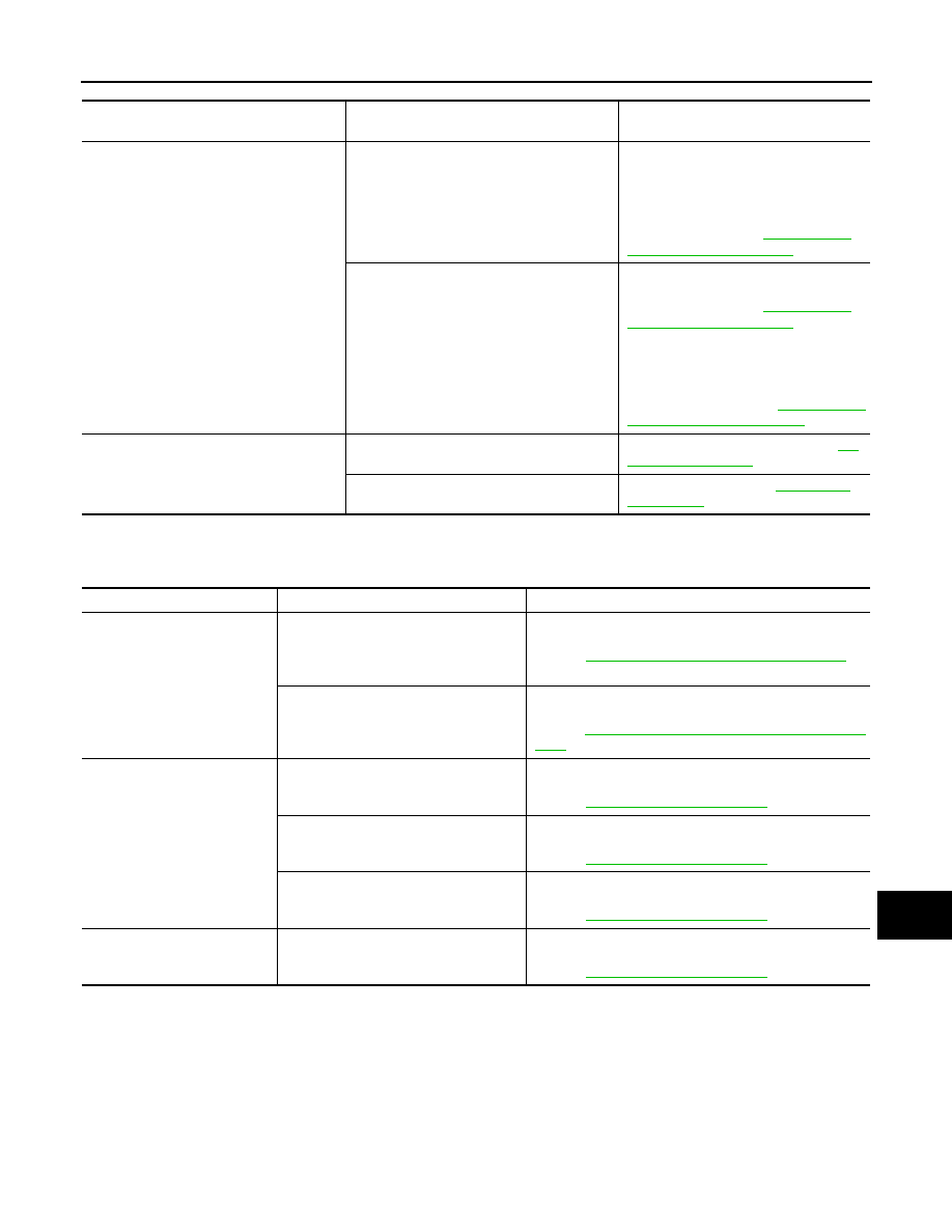
RELATED TO RGB IMAGE

Trouble diagnosis chart by symptom

RELATED TO VOICE CONTROL

Trouble diagnosis chart by symptom

Symptoms

Check items

Probable malfunction location / Action to 

take

The malfunction is detected in the sonar in-
dicator
(Always displayed in red)

The malfunction is detected in only 1 indica-
tor
(Always displayed in red)

• Corner sensor malfunction in corre-

sponding area

• Corner sensor harness circuit in corre-

sponding area

Perform CONSULT-III self-diagnosis of 
sonar system. Refer to 

AV-506, "CON-

SULT-III Function (SONAR)"

.

The malfunction is detected in all 4 indicators 
(Always displayed in red)

• Corner sensor ground circuit.
Perform CONSULT-III self-diagnosis of 
sonar system. Refer to 

AV-506, "CON-

SULT-III Function (SONAR)"

.

• Sonar control unit power supply and 

ground circuits.

• AV communication circuits.
Perform CONSULT-III self-diagnosis of 
multi AV system. Refer to 

AV-498, "CON-

SULT-III Function (MULTI AV)"

.

The sonar indicator is normal, but the buzz-
er does not sound

The buzzer is turned ON when performing 
“Buzzer” in “Active test” of “Sonar”. 

Replace sonar control unit. Refer to 

AV-

929, "Exploded View"

The buzzer is not turned ON when perform-
ing “Buzzer” in “Active test” of “Sonar”.

Replace buzzer. Refer to 

AV-932, "Ex-

ploded View"

.

Symptoms

Check items

Possible malfunction location / Action to take

RGB image is not shown.

• All RGB images are not shown.
• “MULTI AV” is displayed on system se-

lection screen when the CONSULT-III 
is started.

Perform CONSULT-III self-diagnosis.
Refer to 

AV-498, "CONSULT-III Function (MULTI AV)"

.

• All RGB images are not shown.
• “MULTI AV” is not displayed on system 

selection screen when the CONSULT-
III is started.

AV control unit power supply and ground circuit malfunc-
tion.
Refer to 

AV-544, "AV CONTROL UNIT : Diagnosis Proce-

dure"

.

Color of RGB image is not 
proper.

Light blue (Cyan) tint.

RGB signal (R: red) circuit malfunction between AV con-
trol unit and display unit.
Refer to 

AV-550, "Diagnosis Procedure"

.

Purple (Magenta) tint.

RGB signal (G: green) circuit malfunction between AV 
control unit and display unit.
Refer to 

AV-551, "Diagnosis Procedure"

.

Screen looks yellowish.

RGB signal (B: blue) circuit malfunction between AV con-
trol unit and display unit.
Refer to 

AV-552, "Diagnosis Procedure"

.

RGB screen is rolling.

RGB synchronizing signal circuit malfunction between AV 
control unit and display unit.
Refer to 

AV-553, "Diagnosis Procedure"

.

AV-894

< SYMPTOM DIAGNOSIS >

[BOSE AUDIO WITH NAVIGATION]

MULTI AV SYSTEM SYMPTOMS

RELATED TO AUDIO

Trouble diagnosis chart by symptom

RELATED TO iPod

®

Trouble diagnosis chart by symptom

Connect another iPod

®

 and check if the symptom is reproduced or not. If the symptom is reproduced, diag-

nose the vehicle. If no malfunction is detected, replace the iPod harness.
NOTE:

Symptoms

Check items

Probable malfunction location

The voice cannot be controlled 
even if the voice control screen 
is displayed.

Voice sounds at “Voice Microphone Test” 
of Confirmation/Adjustment mode.

AV control unit malfunction.
Replace AV control unit. Refer to 

AV-903, "Exploded 

View"

.

Voice does not sound at “Voice Micro-
phone Test” of Confirmation/Adjustment 
mode.

Microphone circuit malfunction.
Refer to 

AV-560, "Diagnosis Procedure"

.

The voice cannot be controlled
(Voice control screen is not dis-
played).

Steering switch “SOURCE”, “MENU UP”, 
“MENU DOWN”, “ENTER” operates, but 

” does not operate.

Steering switch malfunction.
Replace steering switch.

Steering switch's “SOURCE”, “MENU 

UP”, “MENU DOWN”, “

”, “ENTER” 

does not operate.

Steering switch signal A circuit malfunction.
Refer to 

AV-571, "Diagnosis Procedure"

.

All steering switches do not work.

Steering switch signal GND circuit malfunction.
Refer to 

AV-575, "Diagnosis Procedure"

.

Symptoms

Check items

Possible malfunction location / Action to take

The disk cannot be removed.

Disk eject signal circuit malfunction between AV control 
unit and preset switch.
Refer to 

AV-559, "Diagnosis Procedure"

.

Audio sound is not heard.

No sound from all speakers.

• Amp. ON signal circuit.
• BOSE amp. power supply and ground circuits.

Refer to 

AV-546, "BOSE AMP. : Diagnosis Procedure"

.

Sound is not heard from woofer.

• Woofer power supply and ground circuits.
• Sound signal woofer circuits between BOSE amp. and 

woofer.

• Woofer amp. ON signal circuit between BOSE amp. 

and woofer.

Sound is not heard from center speaker.

Sound signals center speaker circuit.

Sound is heard only from specific places 
(RH front, RH rear, LH front and LH rear).

Sound signal circuits of suspect system.

It does not change to “Driver's 
Audio Stage” mode.

Mode change signal circuit.
Refer to 

AV-558, "Diagnosis Procedure"

.

Satellite radio is not received.

There is malfunction in the CONSULT-III 
self-diagnosis result.

Perform CONSULT-III self-diagnosis.
Refer to 

AV-498, "CONSULT-III Function (MULTI AV)"

.

There is no malfunction in the CON-
SULT-III self-diagnosis result.

Perform the following inspection procedure.
1.

Check satellite radio antenna mounting nut for 
looseness.
NOTE:
Tightening torque: 6.5 N·m (0.66 kg-m, 58 in-lb)

2.

Visually check for satellite radio antenna feeder.

3.

Replace the satellite radio antenna (antenna base).
Refer to 

AV-912, "Exploded View"

.

4.

Replace the AV control unit.
Refer to 

AV-903, "Exploded View"

.

AM/FM radio is not received.

Other audio sounds are normal.

• Antenna amp. ON signal circuit.
• Antenna feeder.

AV

MULTI AV SYSTEM SYMPTOMS

AV-895

< SYMPTOM DIAGNOSIS >

[BOSE AUDIO WITH NAVIGATION]

C

D

E

F

G

H

I

J

K

L

M

B

A

O

P

It is unable to check that between iPod

®

 and iPod harness.

RELATED TO STEERING SWITCH

Trouble diagnosis chart by symptom

RELATED TO AUXILIARY INPUT

NOTE:
Check that there is no malfunction of AUX equipment main body before performing a diagnosis.

Trouble diagnosis chart by symptom

Symptoms

Check items

Possible malfunction location / Action to take

The sound of iPod

®

 is not 

heard.

Other audio sounds are normal.

• iPod sound signal circuits between AV control unit and 

iPod adapter.

• iPod sound signal circuits between iPod

®

 and iPod 

adapter.

It does not change to iPod 
mode.

There is malfunction in the CONSULT-III 
self-diagnosis.

Perform CONSULT-III self-diagnosis.
Refer to 

AV-498, "CONSULT-III Function (MULTI AV)"

.

“iPod is not connected” is dis-
played when it comes to iPod 
mode.

Connected to iPod

®

.

iPod connection recognition signal circuit between iPod

®


and iPod adapter.

iPod

®

 cannot charge the bat-

tery.

iPod battery charge circuit between iPod

®

 and iPod 

adapter.

The title of music file in the iP-

od

®

 is not indicated.

Communication circuit between iPod

®

 and iPod adapter.

Accessing the iPod

®

 is unavail-

able from the vehicle.

Symptoms

Probable malfunction location

None of the steering switch operations work.

Steering switch signal GND circuit malfunction.
Refer to 

AV-575, "Diagnosis Procedure"

.

Only specified switch (1) cannot be operated.

Steering switch malfunction.
Replace steering switch.

Steering switch's “SOURCE”, “MENU UP”, “MENU 

DOWN”,“

”, “ENTER”switches do not work.

Steering switch signal A circuit malfunction.
Refer to 

AV-571, "Diagnosis Procedure"

.

Steering switch's “

”, “VOL UP”, “VOL DOWN”, “

” 

switches do not work.

Steering switch signal B circuit malfunction.
Refer to 

AV-573, "Diagnosis Procedure"

.

Symptoms

Check items

Probable malfunction location

No voice sound is heard when 
AUX mode is selected.

Voice sound is heard when other modes 
are selected.

AUX sound signal circuits (auxiliary input jacks to AV 
control unit).

Image is not displayed when 
AUX mode is selected.

Camera image is displayed.

AUX image signal circuit malfunction.
Refer to 

AV-557, "Diagnosis Procedure"

.

AV-896

< SYMPTOM DIAGNOSIS >

[BOSE AUDIO WITH NAVIGATION]

NORMAL OPERATING CONDITION

NORMAL OPERATING CONDITION

Description

INFOID:0000000003160759

• For Navigation system operation information, refer to Navigation system Owner's Manual.
• Vehicle operation information, refer to Owner's Manual.

BASIC OPERATIONS

NOTE:
Locations stored in the Address Book and other memory functions may be lost if the vehicle's battery is dis-
connected or becomes discharged. If this occurs, service the vehicle's battery as necessary and re-enter the
information in the Address Book. 

RELATED TO VOICE RECOGNITION

Related to basic operation

Related to item choice

The system should respond correctly to all voice commands without difficulty. If problems are encountered, fol-
low the solutions given in this guide for the appropriate error.
Where the solutions are listed b number, try each solution in turn, starting with number one, until the problem
is resolved.

Symptom

Possible cause

Possible solution

No image is displayed.

The brightness is at the lowest setting.

Adjust the brightness of the display.

The system in the video mode.

Push <DISC-AUX> to change the mode. 

The display is turned off.

Push <Day/Night> to turn on the display.

No voice guidance is available. Or 
The volume is too high or too low.

The volume is not set correctly, or it is turned off.

Adjust the volume of voice guidance.

Voice guidance is not provided for certain streets 
(roads displayed in gray).

This is not a malfunction.

No map is displayed on the screen.

A screen other than map screen is displayed.

Push <MAP>.

The screen is too dim. The move-
ment is slow.

The temperature in the interior of the vehicle is low. 

Wait until the interior of the vehicle has 
warmed up.

Some pixels in the display are dark-
er or brighter than others.

This condition is an inherent characteristic of liquid 
crystal displays.

This is not a malfunction.

Some menu items cannot be se-
lected.

Some menu items become unavailable while the ve-
hicle is driven.

Park the vehicle in a safe location, and 
then operate the navigation system.

Symptom

Possible cause

Possible solution

The system does not 
recognize your com-
mand.
or
The system recognizes 
your command incor-
rectly

The interior of the vehicle is too noisy.

Close the windows or have other occupants quiet.

The volume of your voice is too low.

Speak louder

The volume if your voice is too loud.

Speak softer

Your pronunciation is unclear

Speak clearly

You are speaking before the voice recognition made is 
ready

Push and release “

” switch on the steering 

switch, and speak a command after the tone 
sounds

8 seconds or more have passed after you pushed and 

released “

” switch on the steering switch.

Make sure to speak a command within 8 seconds 

after you push and release “

” switch on the 

steering switch. 

Only a limited range of voice commands is usable for 
each screen.

Use a correct voice command appropriate for the 
current screen

The second of the fan od the air conditioner is too loud.

If the air conditioner is set to “Auto”, the fan speed 
is automatically lowered and voice commands 
can be recognized more easily.
Lower the fan speed as necessary or set the air 
conditioner to “Auto”.


Content   ..  276  277  278  279   ..