Infiniti EX35. Manual - part 277
AV
MULTI AV SYSTEM SYMPTOMS
AV-889
< SYMPTOM DIAGNOSIS >
[BOSE AUDIO WITH NAVIGATION]
C
D
E
F
G
H
I
J
K
L
M
B
A
O
P
SYMPTOM DIAGNOSIS
MULTI AV SYSTEM SYMPTOMS
Symptom Table
INFOID:0000000003459047
RELATED TO NAVIGATION
Trouble diagnosis chart by symptom
RELATED TO HANDS-FREE PHONE
• Check that the cellular phone is corresponding type (Bluetooth
®
correspond) when the hands-free related
malfunction vehicle is in service before performing a diagnosis.
• There is a case that malfunction occurs due to the version change of the phone type, etc. even though it is a
corresponding type. Therefore, confirm it by changing the cellular phone to another corresponding type
phone, and check that it operates normally. It is necessary to distinguish whether the cause is the vehicle or
cellular phone.
Simple check for Bluetooth
®
communication
If cellular phone and AV control unit cannot be connected with Bluetooth
®
communication, following procedure
allows the technician to judge which device has malfunction.
1.
Turn on a cellular phone, not connecting Bluetooth
®
communication.
2.
Start CONSULT-III, then start Windows
®
.
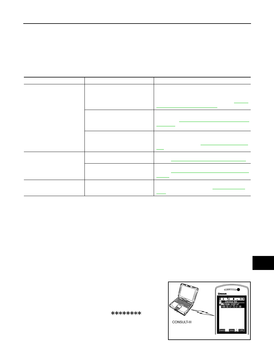
3.
Set CONSULT-III near a cellular phone.
4.
When operated Bluetooth
®
registration by cellular phone, check
if CONSULT-III
*
would be displayed on the device name.
(If other Bluetooth
®
device is located near cellular phone, a
name of the device would be displayed also.)
NOTE:
*:Displayed device name is “NISSAN-
”.
• If no device name is displayed, cellular phone is malfunctioning.
Repair the cellular phone first, then perform diagnosis.
• If CONSULT-III is displayed on device name, cellular phone is nor-
mal. Perform diagnosis as per the following table.
Symptoms
Check items
Possible malfunction location / Action to take
Multifunction switch and preset
switch operation does not work.
• All switches cannot be operated.
• “MULTI AV” is displayed on system
selection screen when the CON-
SULT-III is started.
• Multifunction switch power supply and ground circuit.
• AV communication circuit between AV control unit and
multifunction switch.
Perform CONSULT-III self-diagnosis. Refer to
"CONSULT-III Function (MULTI AV)"
.
• All switches cannot be operated.
• “MULTI AV” is not displayed on sys-
tem selection screen when the CON-
SULT-III is initialized.
AV control unit power supply and ground circuit malfunc-
tion. Refer to
AV-544, "AV CONTROL UNIT : Diagnosis
.
Only specified switch cannot be operat-
ed.
Multifunction switch or preset switch malfunction.
Perform multifunction switch and preset switch self-di-
agnosis function. Refer to
.
Fuel economy display, vehicle set-
ting operation is abnormal.
There is malfunction in the CONSULT-
III self-diagnosis result.
Perform detected DTC self-diagnosis.
Refer to
AV-498, "CONSULT-III Function (MULTI AV)"
.
There is no malfunction in the self-diag-
nosis results.
Ignition signal circuit malfunction.
Refer to
AV-544, "AV CONTROL UNIT : Diagnosis Pro-
.
Guide sound is not heard.
On the setting display select “system
sound (guide sound volume, etc.),” and
confirm that guide sound is ON.
AV control unit malfunction.
Replace AV control unit. Refer to
JPNIA0441GB