Infiniti EX35. Manual - part 1444


  Index      Infiniti     Infiniti EX35 - service repair manual 2008 year


Search            


Content   ..  1442  1443  1444  1445   ..


Infiniti EX35. Manual - part 1444


TM-164

< ON-VEHICLE REPAIR >

[5AT: RE5R05A]

CONTROL VALVE WITH TCM

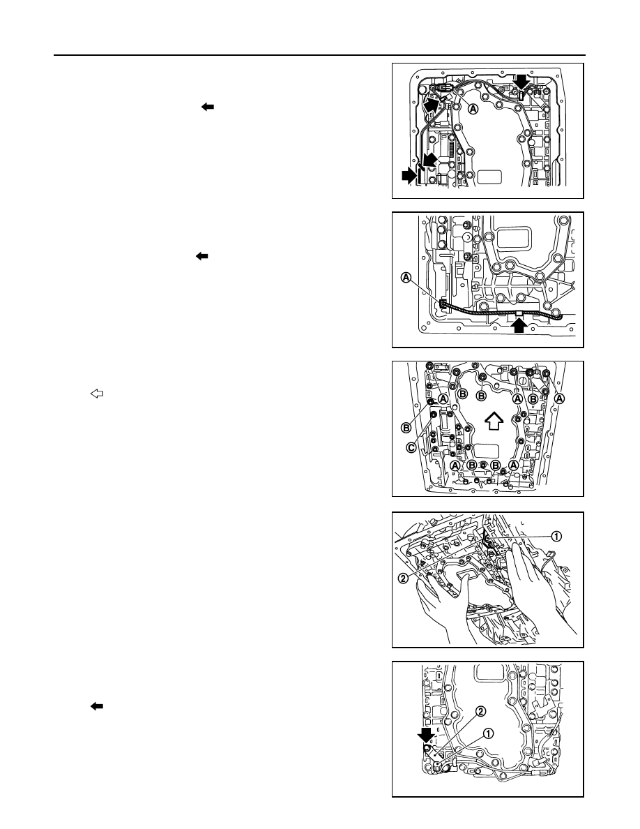
13. Disconnect A/T fluid temperature sensor 2 connector (A).

CAUTION:

Be careful not to damage connector.

14. Disengage terminal clips (

).

15. Disconnect revolution sensor connector (A).

CAUTION:

Be careful not to damage connector.

16. Disengage terminal clip (

).

17. Remove bolts (A), (B) and (C) from control valve with TCM.

18. Remove control valve with TCM from transmission case.

CAUTION:

When removing, be careful with the manual valve (1) notch
and manual plate (2) height. Remove it vertically.

19. Remove A/T fluid temperature sensor 2 (1) with bracket (2) from

control valve with TCM.

SCIA8124E

JPDIA0011ZZ

: Vehicle front

SCIA8074E

JPDIA0012ZZ

: Bolt

JPDIA0013ZZ

CONTROL VALVE WITH TCM

TM-165

< ON-VEHICLE REPAIR >

[5AT: RE5R05A]

C

E

F

G

H

I

J

K

L

M

A

B

TM

N

O

P

20. Remove bracket (1) from A/T fluid temperature sensor 2 (2).

21. Remove O-ring (1) from A/T assembly harness connector (A).

22. Disconnect TCM connectors (A) and (B).

CAUTION:

Be careful not to damage connectors.

23. Remove A/T assembly harness connector (A) from control valve

with TCM using flat-blade screwdriver (B).

24. Disconnect TCM connector (A) and park/neutral position switch

connector (B).

CAUTION:

Be careful not to damage connectors.

JPDIA0014ZZ

JPDIA0015ZZ

JPDIA0016ZZ

JPDIA0017ZZ

JPDIA0018ZZ

TM-166

< ON-VEHICLE REPAIR >

[5AT: RE5R05A]

CONTROL VALVE WITH TCM

INSTALLATION

Note the following, and install in the reverse order of removal.

CAUTION:

• Be careful not to damage connector when installing any connector.
• Do not reuse drain plug gasket.
• Do not reuse O-ring.
• Apply ATF to O-ring.
• Adjust bolt hole of bracket to bolt hole of control valve with TCM when installing A/T fluid tempera-

ture sensor 2 (with bracket).

• Refer to the followings when installing control valve with TCM in transmission case.

CAUTION:

• Make sure that turbine revolution sensor securely installs

turbine revolution sensor hole (B).

• Hang down revolution sensor harness toward outside so as

not to disturb installation of control valve with TCM.

• Adjust A/T assembly harness connector of control valve

with TCM to terminal hole of transmission case.

• Assemble it so that manual valve (1) cutout is engaged with

manual plate (2) projection.

- Install bolts (A), (B) and (C) in control valve with TCM. Tighten bolt

1, 2 and 3 temporarily to prevent dislocation. After that tighten
them in order (1 

 2 

 3), and then tighten other bolts. Tighten

control valve with TCM bolts to the specified torque.

A

: Brake band

JPDIA0020ZZ

JPDIA0012ZZ

: Vehicle front

Bolt symbol

A

B

C

Number of bolts

5

6

1

Length

mm (in)

42 (1.65)

55 (2.17)

40 (1.57)

Tightening torque
N·m (km-g, in-lb)

7.9 (0.81, 70)

With ATF applied

7.9 (0.81, 70)

SCIA8075E

CONTROL VALVE WITH TCM

TM-167

< ON-VEHICLE REPAIR >

[5AT: RE5R05A]

C

E

F

G

H

I

J

K

L

M

A

B

TM

N

O

P

• Refer to the followings when installing oil pan (2) (with oil pan gas-

ket) and clips (1) to transmission case.

CAUTION:

• Do not reuse oil pan gasket and oil pan mounting bolts.
• Install oil pan gasket in the direction to align hole position.
• Install it so that drain plug (3) comes to the position as

shown in the figure.

• Be careful not to pinch harnesses.
• Completely remove all moisture, oil and old gasket, etc. from oil pan mounting surface.

- Tighten oil pan mounting bolts to the specified torque in numerical

order shown in the figure after temporarily tightening them. Tighten
oil pan mounting bolts to the specified torque.

Inspection

INFOID:0000000003130613

INSPECTION AFTER REMOVAL

Check foreign materials in oil pan to help determine causes of mal-
function. If the ATF is very dark, smells burned, or contains foreign
particles, the frictional material (clutches, band) may need replace-
ment. A tacky film that will not wipe clean indicates varnish build up.
Varnish can cause valves, servo, and clutches to stick and can
inhibit pump pressure.
• If frictional material is detected, perform A/T fluid cooler

cleaning. Refer to 

TM-143, "Cleaning"

.

INSPECTION AFTER INSTALLATION

Check for A/T fluid leakage and A/T fluid level after completing installation. Refer to 

TM-141, "Inspection"

.

: Vehicle front

: Oil pan mounting bolt

: Vehicle front

SCIA8117E

JPDIA0021ZZ

SCIA5199E


Content   ..  1442  1443  1444  1445   ..