Infiniti EX35. Manual - part 1340


  Index      Infiniti     Infiniti EX35 - service repair manual 2008 year


Search            


Content   ..  1338  1339  1340  1341   ..


Infiniti EX35. Manual - part 1340


DRIVER AIR BAG MODULE

SR-5

< ON-VEHICLE REPAIR >

C

D

E

F

G

I

J

K

L

M

A

B

SR

N

O

P

4.

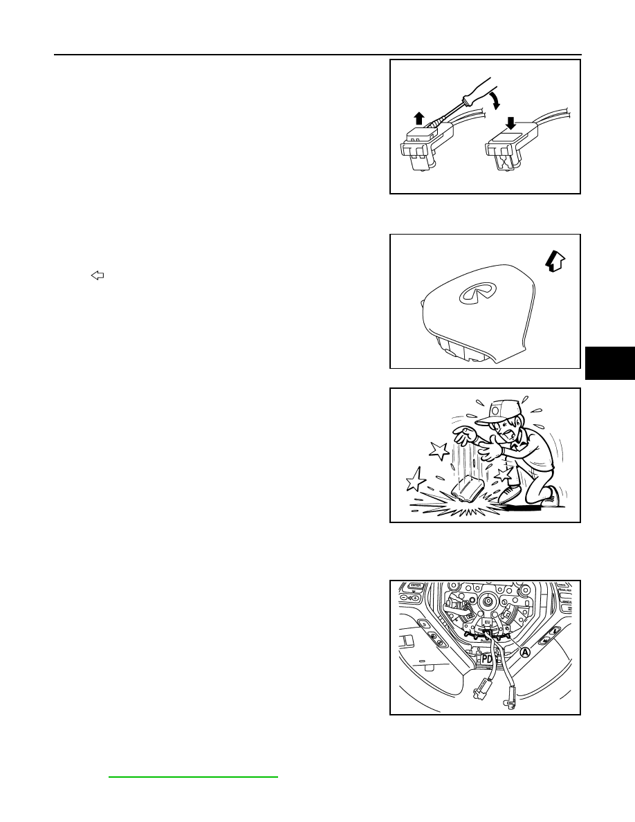
Disconnect driver air bag harness connector.
NOTE:
• For installing/removing driver air bag harness connector, insert

thin screwdriver wrapped in tape into notch, lift lock and
remove connector.

• Install connector with lock raised, and push lock into connec-

tor.

• After installing the connector, check that the lock is pushed

securely into it.

5.

Remove the driver air bag module.

CAUTION:

• Always place driver air bag module with pad side facing

upward.

• Do not insert any foreign objects (screwdriver, etc.) into driver

air bag module.

• Do not disassemble driver air bag module.
• Do not expose the driver air bag module to temperatures

exceeding 90

°

C (194

°

F).

• Do not allow oil, grease or water to come in contact with the

driver air bag module.

• Replace the driver air bag module if it has been dropped or

sustained an impact.

INSTALLATION

Install in the reverse order of removal.

CAUTION:

• Do not use old TORX bolts after removal; replace with new bolts.
• Fix the driver air bag module harness to the harness fixing

hook (A).

• Tighten the TORX bolts after completely adjusting the centers

of fixing holes on the driver air bag module side and the steer-
ing wheel side. If the holes are misaligned, the bolt threads
are damaged and the module is not installed securely.

• In the case that a malfunction is detected by the air bag warning lamp, after reparation or replace-

ment of the malfunctioning parts, reset the memory by self-diagnosis or by the CONSULT-III.

• After the work is completed, check that no system malfunction is detected by air bag warning lamp.

Refer to 

SRC-14, "Diagnosis Description"

.

PHIA0953J

: Upward

JMHIA0539ZZ

JMHIA0009ZZ

JMHIA0540ZZ

SR-6

< ON-VEHICLE REPAIR >

SPIRAL CABLE

SPIRAL CABLE

Exploded View

INFOID:0000000003131584

Removal and Installation

INFOID:0000000003131585

WARNING:

• Before servicing, turn ignition switch OFF, disconnect battery negative terminal and wait at least 3

minutes.

• Do not use air tools or electric tools for servicing.

REMOVAL

1.

Remove the driver air bag module. Refer to 

SR-4, "Removal and Installation"

.

2.

Disconnect steering horn switch harness connector (A).

3.

Remove the steering wheel. Refer to 

ST-16, "Removal and Installation"

.

4.

Remove the steering column cover (upper/lower). Refer to 

IP-12, "Removal and Installation"

.

5.

Remove the spiral cable fixing screws.

1.

Steering column cover upper

2.

Steering column assembly

3.

Steering column cover lower

4.

Driver air bag harness connector

5.

Spiral cable

JMHIA0541ZZ

JMHIA0011ZZ

SPIRAL CABLE

SR-7

< ON-VEHICLE REPAIR >

C

D

E

F

G

I

J

K

L

M

A

B

SR

N

O

P

6.

Disconnect spiral cable body side harness connectors (A).

7.

Pull out forward the spiral cable. 

CAUTION:

• Do not disassemble the spiral cable.
• Do not apply lubricant to the spiral cable.
• Do not allow oil, grease, detergent or water to come in contact with the spiral cable.
• Do not impact the spiral cable by dropping, etc. Replace the

spiral cable if it has been dropped or sustained an impact.

INSTALLATION

Install in the reverse order of removal.

CAUTION:

• The spiral cable may snap during steering operation if the

cable is installed in an improper position. 
The neutral position is set as follows. 

• Turn carefully the spiral cable clockwise to the end position.

Then turn it counterclockwise (about 2 and a half turns) and
stop turning at the point (B) on which the stopper insertion
holes are in the same position.

• The service part is installed in the neutral position by the

stopper and can be set without adjusting after the stopper is
removed.

• Do not over turn the spiral cable or go beyond number of

turns required. (These will cause the cable to snap.)

• Adjust the spiral cable locating pin (A) to the steering wheel

locating pin hole (C).

• In the case that a malfunction is detected by the air bag warning lamp, after reparation or replace-

ment of the malfunctioning parts, reset the memory by self-diagnosis or by the CONSULT-III.

• After the work is completed, check that no system malfunction is detected by air bag warning lamp.

Refer to 

SRC-14, "Diagnosis Description"

.

JMHIA0542ZZ

JMHIA0009ZZ

JMHIA0013ZZ

SR-8

< ON-VEHICLE REPAIR >

FRONT PASSENGER AIR BAG MODULE

FRONT PASSENGER AIR BAG MODULE

Exploded View

INFOID:0000000003131586

Removal and Installation

INFOID:0000000003131587

WARNING:

• Before servicing, turn ignition switch OFF, disconnect battery negative terminal and wait at least 3

minutes.

• Always work from the side of air bag module. Do not work in front of it.
• Do not use air tools or electric tools for servicing.

REMOVAL

1.

Remove the instrument panel assembly. Refer to 

IP-12, "Removal and Installation"

.

2.

Remove the front passenger air bag module fixing screws (A).

3.

Disconnect pawls, and then remove front passenger air bag
module (2) from instrument panel assembly (1).

CAUTION:

1.

Instrument panel assembly

2.

Front passenger air bag module

Refer to 

GI-4, "Components"

 for symbols in the figure

JMHIA0543GB

JMHIA0545ZZ


Content   ..  1338  1339  1340  1341   ..