Content .. 1240 1241 1242 1243 ..
Infiniti EX35. Manual - part 1242
RSU-10
< ON-VEHICLE REPAIR >
REAR SHOCK ABSORBER
REAR SHOCK ABSORBER
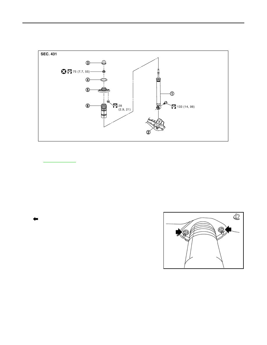
Exploded View
INFOID:0000000003130381
Removal and Installation
INFOID:0000000003130382
REMOVAL
1.
Remove tires with power tool.
2.
Set suitable jack under axle assembly to relieve the coil spring tension.
3.
Remove shock absorber (lower side) with power tool.
4.
Gradually lower the jack to remove it from rear lower link.
5.
Remove shock absorber assembly mounting nuts (upper side)
(
), and then remove shock absorber assembly.
INSTALLATION
Note the following, and install in the reverse order of removal.
• Perform final tightening of bolts and nuts at the shock absorber lower side (rubber bushing), under unladen
conditions with tires on level ground.
Disassembly and Assembly
INFOID:0000000003130383
DISASSEMBLY
CAUTION:
Never damage shock absorber piston rod when removing components from shock absorber.
1.
Remove cap from mounting bracket
1.
Shock absorber
2.
Front lower link
3.
Cap
4.
Mounting seal
5.
Shock absorber mounting bracket
6.
Bound bumper cover
Refer to
for symbols in the figure.
JPEIB0090GB
JPEIB0100ZZ