Content .. 1218 1219 1220 1221 ..
Infiniti EX35. Manual - part 1220
SUNROOF SYSTEM
RF-5
< FUNCTION DIAGNOSIS >
C
D
E
F
G
H
I
J
L
M
A
B
RF
N
O
P
FUNCTION DIAGNOSIS
SUNROOF SYSTEM
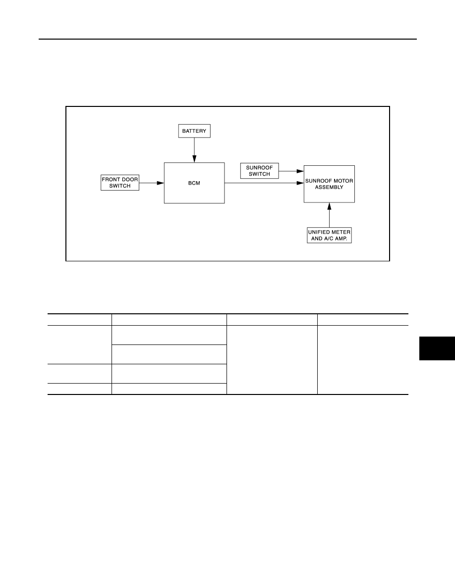
System Diagram
INFOID:0000000003137002
SUNROOF
System Description
INFOID:0000000003137003
SUNROOF SYSTEM
INPUT/OUTPUT SIGNAL CHART
SUNROOF OPERATION
• Sunroof motor assembly operates with the power supply that is output from BCM while ignition switch is ON
or retained power is operating.
• Tilt up/down & slide open/close signals from sunroof switch enables operate sunroof motor to move arbi-
trarily.
• Sunroof motor assembly receives a vehicle speed signal from unified meter and A/C amp. and controls the
sunroof motor torque of tilt-down at the time of high speed operation.
AUTO OPERATION
Sunroof AUTO feature makes it possible to slide open and slide close or tilt up and tilt down the sunroof with-
out holding the sunroof switch in the slide open/tilt down or slide close/tilt up position.
RETAINED POWER OPERATION
• Retained power operation is an additional power supply function that enables sunroof system to operate dur-
ing 45 seconds even when ignition switch is turned OFF.
RETAINED POWER FUNCTION CANCEL CONDITIONS
• Front door CLOSE (door switch OFF)
→
OPEN (door switch ON).
• When ignition switch is ON again.
JMKIA2293GB
Item
Input signal to sunroof motor assembly
Sunroof motor function
Actuator
Sunroof switch
Sunroof switch signal (tilt down or slide
open)
Sunroof control
Sunroof motor
Sunroof switch signal (tilt up or slide
close)
Unified meter and A/
C amp.
Vehicle speed signal
BCM
Retained power signal