Infiniti EX35. Manual - part 1218


  Index      Infiniti     Infiniti EX35 - service repair manual 2008 year


Search            


Content   ..  1216  1217  1218  1219   ..


Infiniti EX35. Manual - part 1218


RAX-12

< ON-VEHICLE REPAIR >

REAR DRIVE SHAFT

Use paint or similar substance for matching marks. Never scratch the surface.

5.

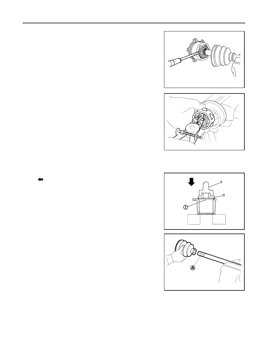
Remove stopper ring with suitable tool, and pull out housing.

6.

Put matching marks on ball cage/steel ball/inner race assembly
and shaft.

CAUTION:

Use paint or similar substance for matching marks. Never
scratch the surface.

7.

Remove snap ring, then remove ball cage/steel ball/inner race
assembly from shaft.

8.

Remove boot from shaft.

ASSEMBLY

1.

Remove old grease on housing with paper waste.

2.

If plug (1) has been removed, use a drift to press in a new one.

3.

Wrap serration shaft with tape (A) to protect the boot from dam-
age. Install boot and boot bands to shaft.

CAUTION:

Never reuse boot and boot band.

4.

Remove the tape wrapped around the serrated on shaft.

SRA249A

SFA514A

: Press

A

: Drift [SST: KV38100500 (

)]

B

: Drift [SST: KV38102200 (

)]

JPDIF0016ZZ

JPDIF0009ZZ

REAR DRIVE SHAFT

RAX-13

< ON-VEHICLE REPAIR >

C

E

F

G

H

I

J

K

L

M

A

B

RAX

N

O

P

5.

Install ball cage/steel ball/inner race assembly (1), align it with
the matching marks on shaft (2) put during the removal.

6.

Secure ball cage/steel ball/inner race assembly onto shaft with
snap ring (3).

CAUTION:

Never reuse snap ring.

7.

Apply the appropriate amount of grease onto housing and slid-
ing surface.

8.

Install stopper ring to housing.

CAUTION:

Never reuse stopper ring.

9.

After installed, pull shaft to check engagement between housing and stopper ring.

10. Install boot securely into grooves (indicated by “*” marks) shown

in the figure.

CAUTION:

If grease adheres to the boot mounting surfaces (indicated
by “*” marks) on shaft or housing, boot may be removed.
Remove all grease from the surfaces.

11. To prevent from deformation of the boot, adjust the boot installa-

tion length (L) to the value shown below by inserting the suitable
tool into the inside of boot from the large diameter side of boot
and discharging inside air.

CAUTION:

• If the boot installation length is outside the standard, it may cause breakage in boot.
• Be careful not to touch the inside of the boot with the tip of tool.

12. Install boot bands securely as shown in the figure. 

CAUTION:

Never reuse boot band.

13. Secure housing and shaft, and then make sure that they are in

the correct position when rotating boot. Install them with boot
band when the mounting positions become incorrect.

CAUTION:

Never reuse boot band.

Inspection

INFOID:0000000003138887

INSPECTION AFTER REMOVAL

• Move joint up/down, left/right, and in the axial direction. Check for any rough movement or significant loose-

ness.

Standard

Grease amount

: Refer to 

RAX-15, "Drive 

Shaft"

.

Standard

L

: Refer to 

RAX-15, "Drive 

Shaft"

.

JPDIG0004ZZ

JPDIF0019ZZ

PDIA1188J

RAX-14

< ON-VEHICLE REPAIR >

REAR DRIVE SHAFT

• Check boot for cracks or other damage, and also for grease leak-

age.

• If a malfunction is found, disassemble drive shaft, and then replace

with new one.

RAA0030D

SERVICE DATA AND SPECIFICATIONS (SDS)

RAX-15

< SERVICE DATA AND SPECIFICATIONS (SDS) 

C

E

F

G

H

I

J

K

L

M

A

B

RAX

N

O

P

SERVICE DATA AND SPECIFICATIONS (SDS)

SERVICE DATA AND SPECIFICATIONS (SDS)

Wheel Bearing

INFOID:0000000003138888

Drive Shaft

INFOID:0000000003138889

Item

Standard

Axial end play

0.05 mm (0.002 in) or less

Joint

Wheel side

Final drive side

Grease quantity

100 – 130 g (3.53 – 4.58 oz)

105 – 125 g (3.70 – 4.40 oz)

Boots installed length

133.5 mm (5.26 in)

130.2 mm (5.13 in)


Content   ..  1216  1217  1218  1219   ..