Content .. 1119 1120 1121 1122 ..
Infiniti EX35. Manual - part 1121
MWI-162
< ON-VEHICLE REPAIR >
COMBINATION METER
ON-VEHICLE REPAIR
COMBINATION METER
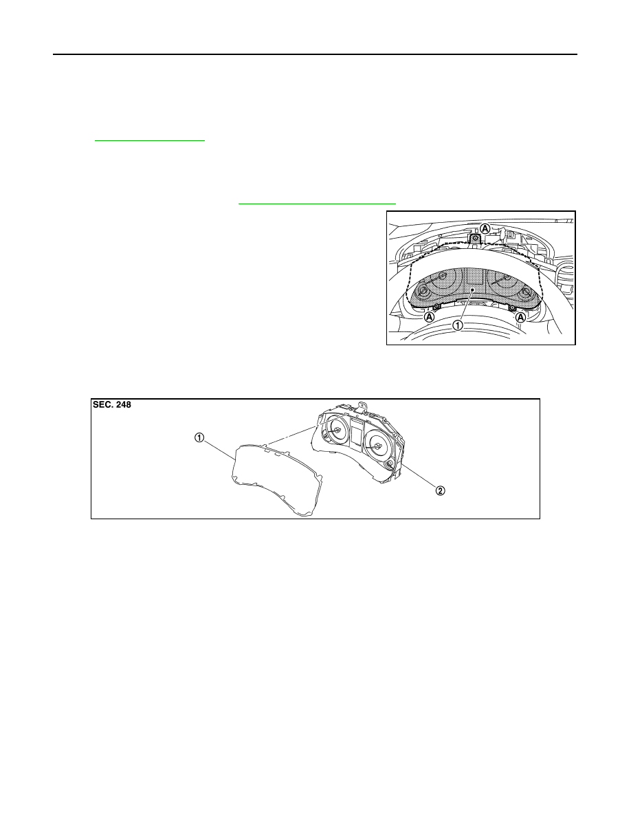
Exploded View
INFOID:0000000003566434
.
Removal and Installation
INFOID:0000000003566435
Removal
1.
Remove the cluster lid A. Refer to
IP-12, "Removal and Installation"
.
2.
Remove screw (A) and connector, and then remove combination
meter (1).
Installation
Install in the reverse order of removal.
Disassembly and Assembly
INFOID:0000000003566436
DISASSEMBLY
Disengage the tabs to separate front cover.
ASSEMBLY
Assemble in the reverse order of disassembly.
JPNIA0865ZZ
JPNIA0866ZZ
1.
Front cover
2.
Unified meter control unit