Hyundai Atos (2002 year). Instruction - part 7
DO-IT-YOURSELF MAINTENANCE
Recommended Spark Plugs:
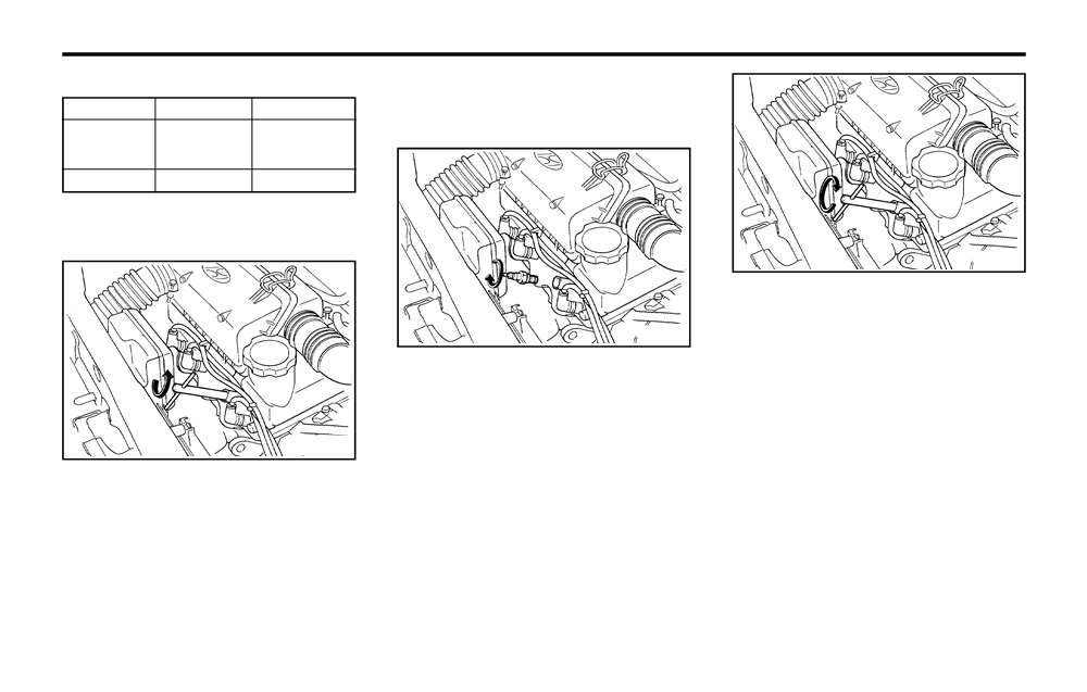
2. To remove the spark plug cable, pull straight
up on the insulated connector, not the cable.
Unleaded
Leaded
Pulling on the cable may damage the carbon
core conductor.
RC9YC4
RC9YC
CHAMPION
RC10YC4
RC10YC
NGK
BKR5ES-11
BKR5ES
G060C02A-AAT
Changing the Spark Plugs
G060C03A
NOTE:
Spark plugs should be tightened firmly. Over-
tightening can damage the threads in the
G060C02A
aluminum cylinder head. Also, leaving them
too loose can cause the spark plug to get
WARNING:
very hot and possibly result in damage to
It is recommended that the engine be cool
the engine.
or cold when changing the spark plugs. If
the engine is hot, you could burn yourself
6. Replace the cable by pushing the insulated
on the insulated connector, the spark plug
connector directly down onto the electrode.
G060C01A
or the engine itself.
Check to be sure it has snapped into place
and can't fall off.
You will find it easier to change spark plugs if
3. When preparing to remove the old spark
the engine is cold. Always change one spark
plug, guide the socket down over the spark
plug at a time. This helps avoid getting the wires
plug, being careful not to damage the ce-
mixed up.
ramic insulator.
4. To remove the old spark plug, turn the
1. Using a clean cloth, remove any dirt that has
wrench handle in a counterclockwise direc-
accumulated around the base of the spark
tion.
plug so it cannot fall into the cylinder when
5. To install the new spark plug, guide the
the spark plug is removed.
socket down over the spark plug, being
careful not to damage the ceramic insulator.
6-8

DO-IT-YOURSELF MAINTENANCE
G070A01X-GAT
G080A02A-AAT
G090A01X-GAT
CHANGING THE AIR CLEANER FIL-
WINDSHIELD WIPER BLADES
FILLING THE WASHER RESERVOIR
TER
(1)
AS60160A
G090A01X
G070A01X
The wiper blades should be carefully inspected
The washer fluid reservoir supplies fluid to the
from time to time and cleaned to remove accu-
windshield washer system.
To change the filter, loosen the clamps (1) on
mulations of road film or other debris. To clean
A good quality washer fluid should be used to fill
the cover. When this is done, the cover can be
the wiper blades and arms, use a clean sponge
the washer reservoir. The fluid level should be
lifted off, the old filter removed and the new filter
or cloth with a mild soap or detergent and water.
checked more frequently during bad weather or
put in its place. Genuine Hyundai replacement
If the wipers continue to streak or smear the
whenever the washer system is in more fre-
parts are recommended.
glass, replace them with Genuine Hyundai
quent use.
Replacement Parts or their equivalent.
The capacity of the washer reservoir is 2.5
CAUTION:
liters (2.63 U.S. quarts).
Operating your vehicle without a proper air
filter in place can result in excessive engine
CAUTION:
wear.
o Do not operate the wipers on dry glass.
CAUTION:
This can result in more rapid wear of the
o Radiator antifreeze
(engine coolant)
wiper blades and may scratch the glass.
should not be used in the washer system
o Keep the blade rubber out of contact
because it will damage the car's finish.
with petroleum products such as engine
o The washer lever should not be pulled
oil, gasoline etc.
and the washer should not be operated if
the washer reservoir is empty. This can
damage the washer fluid pump.
6-9

DO-IT-YOURSELF MAINTENANCE
G100A04X-GAT
G100B01A-AAT
G110A01A-AAT
CHECKING THE TRANSAXLE OIL
To check the Manual Transaxle Fluid
CHECKING THE TRANSAXLE FLUID
Level
(AUTOMATIC)
(MANUAL)
Transaxle fluid in the automatic transaxle should
be checked at those intervals specified in the
vehicle maintenance schedule in Section 5.
Filler plug
G110B01X-AAT
Recommended Fluid
Your Hyundai automatic transaxle is specially
designed to operate with ESSO JWS3314. Dam-
age caused by a nonspecified fluid is not cov-
Drain plug
ered by your new vehicle limited warranty.
SSA6100B
G100A01X
G110C01X-GAT
Park the car on level ground with the engine off.
Transaxle Fluid Capacity
Transaxle lubricant in the manual and transaxle
The fluid capacity of the automatic transaxle is
should be checked at those intervals specified
1. Using a wrench of the correct size, loosen
5.2 liters (5.48 U.S. quarts).
in the vehicle maintenance schedule in Section
the oil filler plug by turning it counterclock-
5.
wise and remove it with your fingers.
WARNING:
Recommended Oil
2. Use your finger or suitable tool to feel inside
The transaxle fluid level should be checked
the hole. The oil level should be at its bottom
when the engine is at normal operating tem-
Use only HYUNDAI GENUINE PARTS MTF
edge. If it is not, check for leaks before
perature. This means that the engine, radia-
75W/90 (API GL-4) in the manual transaxle.
adding oil. To refill the transaxle or bring the
tor, exhaust system etc., are very hot. Exer-
Manual Transaxle Oil Capacity
oil level up, add oil slowly until it reaches the
cise great care not to burn yourself during
The oil capacity of the manual transaxle is 2.45
proper level. Do not overfill.
this procedure.
liters (2.58 U.S. quarts).
3. Replace the plug and washer, screw it in
with your fingers and then tighten securely
WARNING:
with the wrench.
It is always better to check the transaxle oil
level when the engine is cool or cold. If the
engine is hot, you should exercise great
caution to avoid burning yourself on hot
engine or exhaust parts.
6-10

DO-IT-YOURSELF MAINTENANCE
G110D02A-GAT
While the engine is idling, apply the brakes and
WARNING:
To Check the Automatic Transaxle Fluid
move the gear selector lever from "P" to each
The cooling fan is controlled by engine cool-
Level
of its other positions — "R", "N", "D", "2", "L" —
ant temperature and may sometimes oper-
and then return to "N" or "P" with the engine still
ate even when the engine is not running.
idling:
Use extreme caution when working near the
blades of the cooling fan, so that you are not
1.
Open the hood, being careful to keep hands,
injured by a rotating fan blade. As the en-
long hair and clothing clear of any moving
gine coolant temperature decreases, the fan
parts.
will automatically shut off. This is a normal
2.
Remove the transaxle dipstick, wipe it clean,
condition.
reinsert the dipstick as far as it will go, then
remove it again. Now check the fluid level on
G120A01A-AAT
the dipstick. It should be in the "HOT" range
CHECKING THE BRAKES
on the dipstick.
CAUTION:
C090B01X
Because brakes are essential to the safe
operation of the car, it is suggested that
Park the car on level ground with the parking
they be checked and inspected by your
brake engaged. When the transaxle fluid level
Hyundai dealer. The brakes should be
is checked, the transaxle fluid should be at
checked and inspected for wear at those
Fluid level should be within this range
normal operating temperature and the engine
intervals specified in the vehicle mainte-
idling.
nance schedule in Section 5.
G120B01A-AAT
Checking the Brake Fluid Level
WARNING:
G110D03A
Use caution when handling brake fluid. It
can damage your vision if it gets into your
3.
If the transaxle fluid level is low, use a funnel
eyes. It will also damage your vehicle's paint
to add transaxle fluid through the dipstick
if spilled on it and not removed immediately.
tube until the level reaches the "HOT" range.
Do not overfill.
G120C02A-AAT
Recommended Brake Fluid
G110D02A
Use only hydraulic brake fluid conforming to
DOT 3 or DOT 4 specifications in your braking
6-11

DO-IT-YOURSELF MAINTENANCE
system. Follow the instructions printed on the
moisture which can damage the brake sys-
When the air conditioning is being used regu-
container.
tem and cause improper operation.
larly, the compressor drive belt tension should
be checked at least once a month.
G120D01A-AAT
To add brake fluid, first wipe away any dirt then
To check the drive belt tension, press down on
unscrew the fluid reservoir cap. Slowly pour the
To Check the Fluid Level
the belt halfway between the engine crankshaft
recommended fluid into the reservoir. Do not
The fluid level in the brake fluid reservoir should
and compressor pulleys. Pressing with your
overfill. Carefully replace the cap on the reser-
be checked periodically. The level should be
finger, you should not be able to deflect this belt
voir and tighten.
between the "MIN" and "MAX" marks on the
anymore than 5 - 5.5 mm. If you have the
side of the reservoir. If the level is at or below
instruments to check it with a force of 98N (22
G140A01A-AAT
the "MIN" mark, carefully add fluid to bring it up
lb.), the deflection should be approx. 5 - 5.5
AIR CONDITIONER CARE
to "MAX". Do not overfill.
(0.197 - 0.217 inches). If the belt is too loose,
Keeping the Condenser Clean
have it adjusted by your Hyundai dealer.
G120E02A-AAT
The air conditioner condenser (and engine ra-
Adding Brake Fluid
diator) should be checked periodically for accu-
mulation of dirt, dead insects, leaves, etc. These
G140B01A-AAT
can interfere with maximum cooling efficiency.
Checking the Air Conditioning Opera-
When removing such accumulations, brush or
tion
hose them away carefully to avoid bending the
1. Start the engine and let it run at a fast idle for
cooling fans.
several minutes with the air conditioning set
at the maximum cold setting.
G140D01X-GAT
2. If the air coming out of the in-dash vents is
Checking the Compressor Drive Belt
not cold, have the air conditioning system
inspected by your Hyundai dealer.
5 ~ 5.5 mm
CAUTION:
G120E01A
Running the air conditioning system for ex-
tended periods of time with a low refrigerant
WARNING:
level may damage the compressor.
Handle brake fluid carefully. It can damage
your vision if it gets into your eyes. Use only
DOT 3 or DOT 4 specification fluid from a
sealed container. Do not allow the fluid can
Crank pulley
A/C pulley
or reservoir to remain open any longer than
required. This will prevent entry of dirt and
G140D01X
6-12

DO-IT-YOURSELF MAINTENANCE
G140C01A-AAT
G160A01A-GAT
G170A01A-GAT
Lubrication
CHECKING CLUTCH PEDAL
CHECKING BRAKE PEDAL
To lubricate the compressor and the seals in
FREEPLAY
FREEPLAY
the system, the air conditioning should be run
for at least
10 minutes each week. This is
particularly important during cool weather when
the air conditioning system is not otherwise in
use.
6 ~ 13 mm
3 ~ 8 mm
G150A01A-GAT
(0.24 ~ 0.51 in.)
(0.12 ~ 0.31 in.)
CHECKING STEERING WHEEL
FREEPLAY
SSA6160A
SSA6170A
With the engine off, press lightly on the clutch
With the engine off, press down on the brake
pedal until you feel a change in resistance. This
pedal several times to reduce the vacuum in the
30 mm
is the clutch pedal freeplay. The freeplay should
brake booster.
(1.18 in.)
be within the limits specified in the illustration. If
Then, using your hand, press down slowly on
it is not, have it inspected by your Hyundai
the brake pedal until you feel a change in
dealer and adjusted or repaired if necessary.
resistance. This is the brake pedal freeplay.
The freeplay should be within the limits speci-
fied in the illustration. If it is not, have it in-
AS60260A
spected by your Hyundai dealer and adjusted
or repaired if necessary.
To check the steering wheel freeplay, stop the
car with the wheels pointed straight ahead and
gently move the steering wheel back and forth.
Use very light finger pressure and be sensitive
to changes in resistance that mark the limits of
the freeplay. If the freeplay is greater than
specified, have it inspected by your Hyundai
dealer and adjusted or repaired if necessary.
6-13

DO-IT-YOURSELF MAINTENANCE
G180A01A-GAT
G190A01A-GAT
G200A01A-AAT
CHECKING BRAKE PEDAL
CHECKING DRIVE BELTS
CHECKING AND REPLACING
CLEARANCE
Water pump pulley
FUSES
Replacing a Fusible Link
Generator
Bad Good
36 mm (1.42 in.)
9.5~11.0 mm
(0.37 ~ 0.43 in.)
Crankshaft pulley
G190A01A
SSA6180A
Drive belts should be checked periodically for
proper tension and adjusted if necessary. At the
G200A01A
You need a helper to check the brake pedal
clearance. With the engine running, have your
same time, belts should be examined for cracks,
helper press down on the brake pedal several
wear, fraying or other evidence of deterioration
A fusible link will melt if the electrical circuits
times and then hold it down with a force of about
and replaced if necessary.
from the battery are ever overloaded, thus pre-
490N (50kg, 110lbs). The brake pedal clear-
Belt routing should also be checked to be sure
venting damage to the entire wiring harness.
ance is the distance from the top surface of the
there is no interference between the belts and
(This could be caused by a short in the system
brake pedal to the asphalt sheeting under the
other parts of the engine. After a belt is re-
drawing too much current.) If this ever happens,
floor mat.
placed, the new belt should be adjusted again
have a Hyundai dealer determine the cause,
If the brake pedal clearance is not within the
after two or three weeks to eliminate slack
repair the system and replace the fusible link.
limits specified in the illustration, have it in-
resulting from initial stretching after use.
The fusible links are located in a relay box for
spected by your Hyundai dealer and adjusted
easy inspection.
or repaired if necessary.
CAUTION:
When replacing a fusible link, never use
anything but a new fusible link with the
same or lower amperage rating. Never use a
piece of wire or a higher-rated fusible link.
This could result in serious damage and
create a fire hazard.
6-14

DO-IT-YOURSELF MAINTENANCE
G200B01A-AAT
Replacing Accessory Fuse
Fuse Puller
Good
Burned out
SSA6201B
SSA6202B
G200B01A
4.
Replace the blown fuse by pressing a new
CAUTION:
fuse of the same rating into place. The fuse
A burned-out fuse indicates that there is a
The fuse box for the lights and other electrical
should be a snug fit. If it is not, have the fuse
problem in the electrical circuit. If you re-
accessories will be found low on the dashboard
clip repaired or replaced by a Hyundai deal-
place a fuse and it blows as soon as the
on the driver's side. Inside the box you will find
er. If you do not have a spare fuse, you may
accessory is turned on, the problem is seri-
a list showing the circuits protected by each
be able to borrow a fuse of the same or
ous and should be referred to a Hyundai
fuse.
lower rating from an accessory you can
dealer for diagnosis and repair. Never re-
If any of your car's lights or other electrical
temporarily get along without (the radio or
place a fuse with anything except a fuse
accessories stop working, a blown fuse could
cigarette lighter, for example). Always re-
with the same or a lower amperage rating. A
be the reason. If the fuse has burned out, you
member to replace the borrowed fuse.
higher capacity fuse could cause damage
will see that the metal strip inside the fuse has
and create a fire hazard.
burned through. If you suspect a blown fuse,
follow this procedure:
G210A01A-AAT
1. Turn off the ignition and all other switches.
CHECKING THE BATTERY
2. Open the fuse box and examine each fuse.
WARNING:
Remove each fuse by pulling it toward you
Batteries can be dangerous!.
(a small "fuse puller" tool is contained in the
When working with batteries, carefully ob-
fuse box to simplify this operation).
serve the following precautions to avoid
3. Be sure to check all other fuses even if you
serious injuries.
find one that appears to have burned out.
6-15

DO-IT-YOURSELF MAINTENANCE
The fluid in the battery contains a strong solu-
G210B01A-AAT
G230A03A-GAT
tion of sulfuric acid, which is poisonous and
Checking the Battery
POWER STEERING FLUID LEVEL
highly corrosive. Be careful not to spill it on
Keep the battery clean. Any evidence of corro-
yourself or the car. If you do spill battery fluid on
sion around the battery posts or terminals should
yourself, immediately do the following:
be removed using a solution of household bak-
ing soda and warm water. After the battery
o If battery fluid is on your skin, flush the
terminals are dry, cover them with a light coat-
affected areas with water for at least 15
ing of grease.
minutes and then seek medical assistance.
o If battery fluid is in your eyes, rinse out your
G220A01A-AAT
eyes with water and get medical assistance
CHECKING ELECTRIC COOLING
as soon as possible. While you are being
driven to get medical assistance, continue
FANS
to rinse your eyes by using a sponge or soft
WARNING:
G230A01X
cloth saturated with water.
The radiator fan is controlled by engine cool-
The power steering fluid level should be checked
o If you swallow battery fluid, drink a large
ant temperature and may sometimes operate
regularly.
quantity of water or milk followed by milk of
even when the engine is not running. Use
magnesia, eat a raw egg or drink vegetable
extreme caution when working near the blades
To check the power steering fluid level, be sure
oil. Get medical assistance as soon as
of the cooling fan, so that you are not injured
the ignition is "OFF", then check to make cer-
possible.
by a rotating fan blade. As the coolant tem-
tain that the power steering fluid level is be-
tween the "MAX" and "MIN" level markings on
perature decreases the fan will automatically
While batteries are being charged (either by a
shut off. This is a normal condition.
the fluid reservoir.
battery charger or by the vehicle's alternator),
they produce explosive gases. Always observe
G220B01A-AAT
NOTE:
these warnings to prevent injuries from occur-
Checking Engine Cooling Fan
Grinding noise from the power steering
ring:
pump may be heard immediately after the
The engine cooling fan should come on auto-
engine is started in extremely cold condi-
matically if the engine coolant temperature is
o Charge batteries only in a well ventilated
tions (below -20°C). If the noise stops dur-
high.
area.
ing warm up, there is no abnormal function
o Do not permit flames, sparks or smoking in
G220C01A-AAT
in the system. This is due to a power steer-
the area.
Checking Condenser Cooling Fan
ing fluid characteristic in extremely cold
o Keep children away from the area.
conditions.
The condenser cooling fan should come on
automatically whenever the air conditioning is
in operation.
6-16

DO-IT-YOURSELF MAINTENANCE
G270A02X-GAT
WARNING:
Recommended Fluid
HEADLIGHT BULB
The halogen bulb contains gas under pres-
Use PSF-3 type fluid.
sure and if impacted could shatter, and re-
sulting in flying fragments. Always wear eye
NOTE:
protection when servicing the bulb. Protect
Do not start the engine when the power
the bulb against abrasions or scratches and
steering oil reservoir is empty.
against liquids when lighted. Turn the bulb
on only when installed in a headlight. Re-
G240A01A-AAT
place the headlight if damaged or cracked.
POWER STEERING HOSES
Keep the bulb out of the reach of children
It is suggested that you check the power steer-
and dispose of the used bulb with care.
ing hose connections for fluid leakage at those
intervals specified in the vehicle maintenance
schedule in Section 5.
G270A01X
G290A02X-GAT
The power steering hoses should be replaced if
HEADLIGHT AIMING ADJUSTMENT
there is severe surface cracking, pulling, scuff-
Replacement instructions:
Before performing aiming adjustment, make sure
ing or worn spots. Deterioration of the hose
of the following.
1.
Allow the bulb to cool. Wear eye protection.
could cause premature failure.
2.
Always grasp the bulb by its base, avoid
1.
Keep all tires inflated to the correct pres-
touching the glass.
G260A03A-AAT
3.
Disconnect the connector, then remove the
sure.
2.
Place the vehicle on level ground and press
REPLACING HEADLIGHT BULBS
dust cover.
the front bumper & rear bumper down sev-
Before attempting to replace a headlight bulb,
4.
Push the bulb spring for removing the head-
eral times. Place the vehicle at a distance of
be sure the switch is turned to the "OFF"
light bulb.
3,000 mm (118 in.) from the test wall.
position.
5.
Remove the headlight bulb. If the bulb is
3.
See that the vehicle is unloaded (except for
The next paragraph shows how to reach head-
burned out, replace it with the same watt-
full levels of coolant, engine oil and fuel, and
light bulbs so they may be changed. Be sure to
age.
spare tire, jack, and tools). Have the driver
replace the burned-out bulb with one of the
6.
Installation is the reverse order of the re-
or equivalent weight placed in driver's seat.
same number and wattage rating.
moval.
7.
Use the protective cap and carton to promptly
CAUTION:
dispose of the old bulb.
Keep the lamps out of contact with petro-
8.
Check for proper headlight aim.
leum product, such as oil, gasoline, etc.
6-17

DO-IT-YOURSELF MAINTENANCE
G290B02X-GAT
SPECIFICATIONS:
Vertical aiming
Adjustment After Headlight Assembly
Replacement
"H"
Horizontal center line of headlights from
30mm(1.18in.)
Vertical
ground : 646 mm (25.43 in.)
Horizontal line
line
W
15mm (0.59in.)
"W"
"P"
Distance between each headlight center:
988 mm (38.89 in.)
H
"L"
Cut-off line
Distance between the headlights and the
G290A02Y
wall that the lights are tested against:
Ground line
3,000 mm (118 in.).
4.
Clean the head light lenses and turn on the
L
H
headlights (Low beam).
G290B01Y
5.
Open the hood.
6.
Draw the vertical line (through the center of
If the vehicle has had front body repair and the
each headlight beam pattern) and the hori-
headlight assembly has been replaced, the
zontal line (through the center of each head-
headlight aiming should be checked using the
light beam pattern) on the aiming screen.
aiming screen as shown in the illustration. Turn
on the headlight switch. (Low Beam Position)
And then, draw the horizontal parallel line at
30 mm (1.18 in.) under the horizontal line.
1. Adjust headlights so that main axis of light is
7.
Adjust each cut-off line of the low beam to
parallel to center line of the body and is
the parallel line with a phillips screwdriver -
aligned with point "P" shown in the illustra-
VERTICAL AIMING.
tion.
2. Dotted lines in the illustration show the cen-
8.
Adjust each cut-off line of the low beam to
ter of headlights.
the each vertical line with a phillips screw-
driver - HORIZONTAL AIMING.
6-18

DO-IT-YOURSELF MAINTENANCE
G280A01X-GAT
(ATOS)
6
11
7
9
1
2
3
4
5
10
8
G280A02X
No.
Part Name
Wattage
No.
Part Name
Wattage
1
Front Fog Light
55
8
Luggage Compartment Light
5
2
Headlight
60/55
9
License Plate Light
5
3
Front Position Light
5
10
Rear Fog Light
21
4
Front Turn Signal Light
21
11
Rear Combination Light
5
Side-Repeater Light (If installed)
5
Turn Signal Light
21
6
Interior Light
8
Stop/Tail Light
21/5
7
High Mounted Rear Stop Light (If Installed)
21
Back-up Light
21
6-19

DO-IT-YOURSELF MAINTENANCE
G280A02V-GAT
(ATOS PRIME)
6
11
7
9
1
2
3
4
5
10
8
G280A03V
No.
Part Name
Wattage
No.
Part Name
Wattage
1
Front Fog Light
55
8
Luggage Compartment Light
5
2
Headlight
60/55
9
License Plate Light
5
3
Front Position Light
5
10
Rear Fog Light
21
4
Front Turn Signal Light
21
11
Rear Combination Light
5
Side-Repeater Light (If installed)
5
Turn Signal Light
21
6
Interior Light
8
Stop/Tail Light
21/5
7
High Mounted Rear Stop Light (If Installed)
2.6
Back-up Light
21
6-20

EMISSION CONTROL SYSTEMS
the crankcase through the air intake hose.
H010D01A-AAT
7. EMISSION CON-
Inside the crankcase, the fresh air mixes with
3. Exhaust Emission Control System
blow-by gases, which then pass through the
The exhaust emission control system is a high-
TROL SYSTEMS
PCV valve and into the induction system.
ly effective system which controls exhaust emis-
sion while maintaining good vehicle perfor-
mance.
H010C02A-GAT
H010A01A-GAT
H020A01A-GAT
2. Evaporative Emission Control
EMISSION CONTROL SYSTEM
CATALYTIC CONVERTER (If Installed)
System (If installed)
(If Installed)
The Evaporative Emission Control System is
Your Hyundai is equipped with an emission
designed to prevent fuel vapors from escaping
control system to meet all requirements of the
into the atmosphere.
Emission prohibition rules of your province.
There are three emission control systems which
Canister
are as follows.
While the engine is inoperative, fuel vapors
1) Crankcase emission control system
generated inside the fuel tank are absorbed and
2) Evaporative emission control system
stored in the onboard canister. When the en-
3) Exhaust emission control system
gine is running, the fuel vapors absorbed in the
canister are drawn into the induction system
Catalytic Converter
In order to assure the proper function of the
through
H020A01A
emission control systems, it is recommended
the purge control solenoid valve.
that you have your car inspected and main-
The catalytic converter is part of the exhaust
7
tained by an authorized Hyundai dealer in ac-
emission control system. It's purpose is to re-
cordance with the maintenance schedule in this
Purge Control Solenoid Valve
move certain engine emission products from
manual.
The purge control solenoid valve is controlled
the engine's exhaust. It looks something like a
by the ECM; when the engine coolant temper-
muffler and is located underneath the car in the
ature is low, and during idling, it closes, so that
exhaust system.
H010B01A-AAT
evaporated fuel is not taken into the engine.
1. Crankcase Emission Control Sys-
After engine warm-up, during ordinary driving, it
tem
opens so as to introduce evaporated fuel to the
The Positive Crankcase Ventilation System is
engine.
employed to prevent air pollution caused by
blow-by gases being emitted from the crank-
case. This system supplies fresh filtered air to
7-1
EMISSION CONTROL SYSTEMS
H020B01A-GAT
o
Do not touch the catalytic converter or any
About the Catalytic Converter
other part of the exhaust system while the
Exhaust gases passing through the catalytic
engine is running as it is very hot and could
converter cause it to operate at very high tem-
result in burns.
peratures. As a result, the introduction of large
o
Remember that your Hyundai dealer is your
amounts of unburned gasoline may cause it to
best source of assistance.
overheat and create a fire hazard.
This can be avoided by observing the following:
o
Use unleaded fuel only.
o
Maintain your engine in good condition. Ex-
tremely high converter temperatures can
result from improper operation of the electri-
cal, ignition or fuel injection systems.
o
If your engine stalls, pings, knocks, or is
hard to start, take your car to your Hyundai
dealer as soon as possible and have the
difficulty corrected.
o
Avoid driving with a very low fuel level. If you
run out of gasoline, it could cause the engine
to misfire and result in excessive loading of
the catalytic converter.
o
Avoid idling the engine for periods longer
than 10 minutes.
o
Your Hyundai should not be either pushed
or pulled to get it started.
This can cause the catalytic converter to
overload.
o
Take care not to stop your Hyundai over any
combustible material such as grass, paper,
leaves or rags. As these materials could
come in contact with the catalytic converter
and could cause a fire.
7-2

CONSUMER INFORMATION
I010B01A-AAT
I030A01X-GAT
8. CONSUMER IN-
Engine Number
RECOMMENDED INFLATION PRES-
SURES
FORMATION
I010A01A-GAT
VEHICLE IDENTIFICATION NUMBER
(VIN)
I010B01A
I030A01S
The engine number is stamped on the engine
block as shown in the drawing.
The tire label located on the driver side center
pillar outer panel gives the tire pressures rec-
ommended for your vehicle.
I020A01A-AAT
TIRE INFORMATION
PRESSURE. kPa (PSI)
The tires supplied on your new Hyundai are
RIM
TIRE
UP TO 2
UP TO MAX.
chosen to provide the best performance for
SIZE
SIZE
PERSONS
LOAD
I010A01A
normal driving.
FRONT
REAR
FRONT
REAR
4.0BX13
155/70R13
207(30)
207(30)
221(32)
221(32)
The vehicle identification number (VIN) is the
8
4.5JX13
155/70R13
207(30)
207(30)
221(32)
221(32)
number used in registering your car and in all
5.0JX13
175/60R13
207(30)
207(30)
221(32)
221(32)
legal matters pertaining to its ownership, etc.
It can be found on the identification plate at-
These pressures were chosen to provide the
tached to the engine side of the firewall be-
most satisfactory combination of ride comfort,
tween the engine and passenger compartment.
tire wear and stability under normal conditions.
Tire pressures should be checked at least
monthly. Proper tire inflation pressures should
be maintained for these reasons:
8-1

CONSUMER INFORMATION
o Lower-than-recommended tire pressures
I040A01A-GAT
I060A01A-GAT
cause uneven tread wear and poor han-
SNOW TIRES
TIRE ROTATION
dling.
If you equip your car with snow tires, they
o Higher-than-recommended tire pressures
should be the same size and have the same
increase the chance of damage from im-
load capacity as the original tires. Snow tires
pacts and cause uneven tread wear.
should be installed on all four wheels; other-
wise, poor handling may result.
CAUTION:
Snow tires should carry 28 kPa (4 psi) more air
Always observe the following:
pressure than the pressure recommended for
the standard tires on the tire label on the driver
o
Check pressures when the tires are cold.
side center pillar outer panel, or up to the
That is, after the car has been parked for
maximum pressure shown on the tire sidewall
at least three hours and hasn't been driv-
whichever is less.
en more than 1.6 km or one mile since
SSA8050A
Do not drive faster than the speed limit when
starting up.
your car is equipped with snow tires.
o
Check the pressure of your spare tire
Tires should be rotated every 10,000 km (6,000
each time you check the pressure of
miles). If you notice that tires are wearing un-
other tires.
I050A01X-GAT
evenly between rotations, have the car checked
o
Never overload your car. Be especially
TIRE CHAINS
by a Hyundai dealer so the cause may be
careful about overloading if you equip
Tire chains, if necessary, should be installed on
corrected.
your car with a luggage rack or car top
the front wheels. Be sure that the chains are the
After rotating, adjust the tire pressures and be
carrier.
proper size and that they are installed in accor-
sure to check wheel nut tightness.
dance with the manufacturer's instructions.
WARNING:
To minimize tire and chain wear, do not con-
Do not mix bias-ply and radial-ply tires un-
tinue to use tire chains when they are no longer
der any circumstances.
needed.
This may cause dangerous handling char-
acteristics.
WARNING:
When driving on roads covered with snow
or ice, drive at less than 30 km/h (20 mph).
8-2