Hummer H1 (2002+). Manual - part 168


  Index      Hummer     Hummer H1 - service repair manual 2002 year


Search            


Content   ..  166  167  168  169   ..


Hummer H1 (2002+). Manual - part 168


_____________________________________________________________________


 Body  10-43


®


05745159


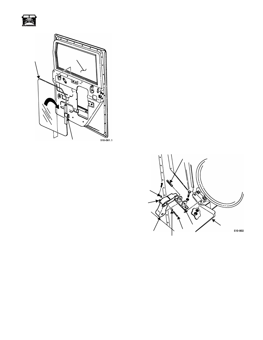
Figure 10-73:   Glass/Lift Channel Bracket 

Location


Door Glass “Wind Noise” Diagnosis and 
Repair/Side Window Alignment


Wind noise or whistle generating from the side windows at
highway speeds is the result of inadequate sealing of the glass
at the upper seal. The glass must be properly aligned in the
window opening, adjust door glass as follows:.

1.

Loosen, but do not remove, lift channel bracket mounting 
bolts.

2.

Place block of wood (or equivalent symmetrical object)
across upper seal of window opening.

3.

Roll window up so that glass contacts block of wood and
squares itself on window opening.

4.

Tighten lift channel bracket mounting bolts.

5.

Verify proper window operation.


HOOD, HOOD LATCH, AND PROP ROD

Hood Latch and Bracket Replacement


Removal 


NOTE: 


If only the rubber latch is to be replaced, the spring pin

does not have to be completely out of base.

1.

Remove spring pin and rubber latch from base (Figure 10-74).

2.

Remove two locknuts, washers, bolts, washers, and base
from body. 

3.

Remove five locknuts, washers, bolts, latch bracket, latch
plate, and hood latch stop bracket from hood. Discard
locknuts  (Figure 10-74).


Disassembly 


Remove cotter pin, spring pin, two rollers, and hood latch from
rubber latch (Figure 10-74).


Assembly 


Secure hood latch to rubber latch with two rollers, pin, and cot-
ter pin (Figure 10-74).


Figure 10-74:   Hood Latch Replacement


Installation 


1.

Secure latch plate and hood latch stop bracket to hood with 
three bolts, washers, and locknuts. Tighten locknuts to 10 
lb-ft (14 N•m) (Figure 10-74).

2.

Secure latch bracket to latch plate with two bolts, washers,
and locknuts. Tighten locknuts to 10 lb-ft (14 N•m).

3.

Apply sealing compound before securing base to body
with two washers, bolts, washers, and locknuts. Tighten
bolts to 6 lb-ft (8 N•m) (Figure 10-74).

4.

Secure rubber latch to base with spring pin.

GLASS

WINDOW

LIFT CHANNEL BRACKET

SPRING PIN

BODY

BASE

PIN

ROLLER

RUBBER

HOOD 

ROLLER

LATCH

LATCH


Section 10   Body


10-44

Body


______________________________________________________________________


®


Figure 10-75:   Hood Latch Bracket and Latch Plate

Replacement


Hood Release Cable Assembly Replacement


Removal


1.

Raise and secure hood.

2.

Remove cable handle, two nuts, lockwasher, nut, and
cable assembly from cable mounting bracket.

3.

Remove cable assembly from cable clamp bracket
(Figure 10-77).

4.

Remove cable assembly and grommet from body.

5.

Remove lock pin from cable assembly.


Installation


1.

Install lock pin on cable assembly (Figure 10-77).

2.

Secure cable assembly to cable clamp bracket.

3.

Secure cable assembly to cable mounting bracket with nut,
lockwasher, two nuts, and cable handle (Figure 10-76).

4.

Install grommet and cable assembly on body and apply
sealer around cable and grommet.

5.

Lower hood.


Figure 10-76:   Hood Release Handle Assembly

Mounting

Figure 10-77:   Hood Release Cable Assembly


Hood Release Latch and Bracket Assembly 
Replacement


Removal


1.

Raise and secure hood.

2.

Remove two bolts, lockwashers, and latch assembly from
hood (Figure 10-78).

3.

Remove pin, spring, and lock arm from latch assembly
(Figure 10-79).

4.

Remove cable assembly from cable clamp bracket
(Figure 10-77).

5.

Remove three nuts, lockwashers, bolts, and bracket
assembly from body (Figure 10-80).

LATCH 

LATCH

HOOD

HOOD LATCH 

STOP BRACKET

BRACKET

PLATE

HANDLE


BRACKET

 MOUNTING

CABLE

CABLE

ASSEMBLY

WASHER

9-S10-001

LOCK

CABLE ASSEMBLY

GROMMET

BODY

APPLY 

SEALER

CABLE CLAMP

BRACKET

PIN


_____________________________________________________________________


 Body  10-45


®


05745159

6.

Remove two nut and lockwasher assemblies, screws, cable
clamp bracket, and spacer from bracket assembly.

7.

Inspect three nylon bushings in bracket assembly. Remove
and discard bushings if damaged.


Figure 10-78:   Hood Release Latch and 

Bracket Assembly Mounting

Figure 10-79:   Latch Assembly Breakdown

Figure 10-80:   Cable Clamp Bracket Assembly

Breakdown


Installation


1.

Insert three nylon bushings into bracket assembly, if 
removed (Figure 10-80).

2.

Secure spacer and cable clamp bracket to bracket
assembly with two screws and nut and lockwasher
assemblies.

3.

Secure bracket assembly to body with three bolts,
lockwashers, and nuts.

4.

Secure cable assembly to cable clamp bracket
(Figure 10-77). Seal grommet with silicone sealer.

5.

Secure spring and lock arm to latch assembly with pin
(Figure 10-79).

6.

Secure latch assembly to hood with two lockwashers and
bolts (Figure 10-78).

7.

Lower hood.


Hood Prop Rod and Bracket Replacement


Removal 


WARNING:  To avoid injury or damage to equipment,
support hood during hood prop rod and bracket re-
placement.


1.

Raise and support hood.

2.

Remove cotter pin, two washers, and hood prop rod from
hood (Figure 10-81).

3.

Remove four screws, lockwashers, bracket, and hood prop
rod from airlift bracket (Figure 10-82).

HOOD

LATCH

PROP ROD

 ASSEMBLY

SPRING

LOCK ARM

LATCH

PIN

 ASSEMBLY

9-S10-002

CABLE CLAMP

 BRACKET

BODY

CABLE 

ASSEMBLY

NUT AND 

LOCKWASHER 

ASSEMBLY

 BRACKET 
ASSEMBLY

SPACER


10-46

Body


______________________________________________________________________


®


Figure 10-81:   Hood Prop Rod Replacement

Figure 10-82:   Hood Prop Rod and Bracket 

Replacement


Disassembly 


1.

Remove hood prop rod from eyebolt (Figure 10-83).

2.

Remove locknut, washer, bushing, spring, snapring,
bushing, washer, and eyebolt from bracket.


Cleaning and Inspection 


NOTE: 


Clean all components, and examine for wear or dam-

age. Replace if necessary.

Inspect two bushings and spring for cracks, wear, or distortion
(Figure 10-83).


Assembly 


1.

Secure bushing to bracket with snapring (Figure 10-83).


NOTE: 


Length of spring with bracket assembled is 2-1/4 in.

(5.7 cm).

2.

Secure washer, eyebolt, spring, bushing, washer, and
locknut to bracket.

3.

Install hood prop rod into eyebolt.


Figure 10-83:   Hood Prop Rod and Bracket Assembly 

Breakdown


Installation 


1.

Secure hood prop rod and bracket to airlift bracket with 
four lockwashers and screws. Tighten screws to 6 lb-ft 
(8 N•m)  (Figure 10-82).

2.

Secure hood prop rod to hood with two washers and cotter
pin (Figure 10-81).

3.

Lower hood.

HOOD 

HOOD

PROP ROD

HOOD 

AIRLIFT BRACKET

BRACKET

PROP ROD

BUSHING

SPRING

BRACKET

BUSHING

HOOD 

EYEBOLT

SNAPRING

PROP ROD


Content   ..  166  167  168  169   ..