Honda Odyssey 2004. Manual - part 603


  Index      Honda     Honda Odyssey 2004 - service repair manual 2004 year


Search            


Content   ..  601  602  603  604   ..


Honda Odyssey 2004. Manual - part 603


12

13

14

YES

NO

YES

NO

23-354

SRS

Symptom Troubleshooting (cont’d)

A

A

N

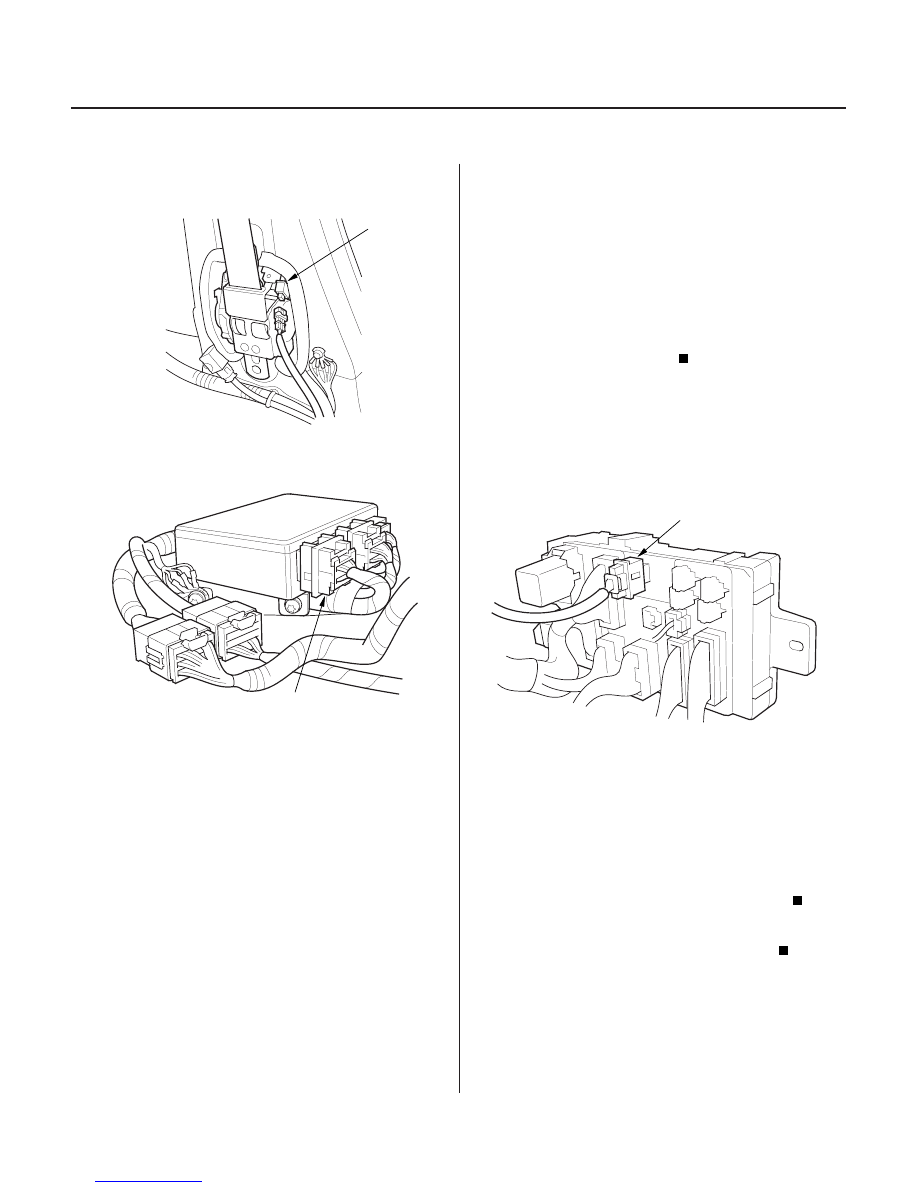
10. Disconnect both seat belt tensioner 2P connectors

(A).

11. Disconnect SRS unit connector A (18P) from the

SRS unit.

12. Reconnect the negative battery cable.

13. Turn the ignition switch ON (II), and wait for 30

seconds. Then turn the ignition switch OFF.

14. Check the No. 2 (10A) fuse in the under-dash

fuse/relay box.

Short to ground in the SRS unit; replace the

SRS unit (see page 23-382).

Go to step 15.

15. Replace the No. 2 (10A) fuse in the under-dash

fuse/relay box.

16. Disconnect the driver’s under-dash fuse/relay

connector N from the under-dash fuse/relay box.

17. Turn the ignition switch ON (II), and wait for 30

seconds. Then turn the ignition switch OFF.

18. Check the No. 2 (10A) fuse in the under-dash

fuse/relay box.

Short to ground in the SRS main harness or

SRS floor harness; replace the faulty harness.

Short to ground in the under-dash fuse/relay

box; replace the under-dash fuse/relay box.

Is the f use OK ?

Is the f use OK ?

03/07/29 10:42:33 61S0X050_230_0354

15

16

17

18

23-355

A

A

A

A

19. Turn the ignition switch OFF. Disconnect the

battery negative cable, and wait for 3 minutes.

20. Disconnect the driver’s airbag 4P connector (A).

21. Disconnect the front passenger’s airbag 4P

connector (A).

22. Disconnect both seat belt tensioner 2P connectors

(A).

23. Disconnect SRS unit connector A (18P) from the

SRS unit.

(cont’d)

03/07/29 10:42:34 61S0X050_230_0355

19

*09

*10

22

YES

NO

YES

NO

23-356

SRS

Symptom Troubleshooting (cont’d)

SRS UNIT CONNECTOR A (18P)

N

SRS UNIT CONNECTOR A (18P)

DASHBOARD WIRE HARNESS 2P CONNECTOR

BLK/WHT

C

24. Reconnect the battery negative cable.

25. Connect a voltmeter between the No. 3 terminal of

SRS unit connector A (18P) and body ground. Turn
the ignition switch ON (II), and measure the voltage.
There should be battery voltage.

Go to step 29.

Go to step 26.

26. Turn the ignition switch OFF.

27. Disconnect the driver’s under-dash fuse/relay box

connector N from the under-dash fuse/relay box.

28. Check resistance between the No. 3 terminal of

SRS unit connector A (18P) and the No. 2 terminal
of the dashboard wire harness 2P connector. There
should be 0

1.0

.

Open in the under-dash fuse/relay box or

poor contact at the SRS main harness 2P
connector; check the connection. If the connection
is OK, replace the under-dash fuse/relay box.

Open in SRS main harness or SRS floor

harness; replace the faulty harness.

29. Turn the ignition switch OFF.

30. Disconnect SRS unit connector C (8P) from the SRS

unit.

Wire side of female terminals

Wire side of female terminals

Wire side of
female terminals

Is ther e batter y voltage?

Is the r esistance as specif ied?

03/07/29 10:42:35 61S0X050_230_0356

23

24

25

YES

NO

YES

NO

YES

NO

23-357

SRS UNIT CONNECTOR C (8P)

SRS UNIT CONNECTOR A (18P)

JUMPER
WIRE

C

SRS UNIT CONNECTOR C (8P)

31. Connect the No. 3 terminal of SRS unit connector A

(18P) and the No. 5 terminal of the SRS unit
connector C (8P) with a jumper wire.

32. Turn the ignition switch ON (II).

33. Check the SRS indicator.

Faulty SRS unit; replace the SRS unit (see

page 23-382).

Go to step 34.

34. Turn the ignition switch OFF.

35. Disconnect the jumper wire between the No. 3

terminal of SRS unit 18P connector A (18P) and the
No. 5 terminal of the SRS unit connector C (8P).

36. Check the No. 2 (10A) fuse in the under-dash

fuse/relay box.

Go to step 40.

Go to step 37.

37. Replace the No. 2 (10A) fuse in the under-dash fuse

/relay box.

38. Remove the gauge assembly (see page 22-100),

then disconnect gauge assembly connector C (16P)

39. Check resistance between the No. 5 terminal of

SRS unit connector C (8P) and body ground. There
should be an open circuit, or at least 1 M

.

Faulty SRS indicator circuit in the gauge

assembly; replace the gauge assembly.

Go to step 45.

(cont’d)

Wire side of female terminals

Wire side of female terminals

Wire side of female terminals

Does the SRS indicator go of f ?

Is the f use OK ?

Is the r esistance as specif ied?

03/07/29 10:42:35 61S0X050_230_0357

from the gauge assembly.


Content   ..  601  602  603  604   ..