Honda Odyssey 2004. Manual - part 595
−
−
08
09
YES
NO
23-322
SRS
DTC Troubleshooting (cont’d)
C
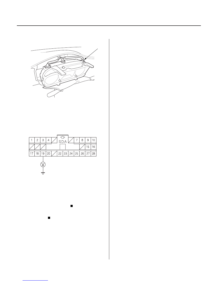
SRS UNIT CONNECTOR A (28P)
BLU
11. Reconnect gauge assembly connector C (16P).
12. Reconnect the battery negative cable.
13. Connect a voltmeter between the No. 19 terminal of
SRS unit connector A (28P) and body ground. Turn
the ignition switch ON (II), and measure voltage.
There should be 1.6 V or less.
Open in the SRS indicator circuit or poor
contact at gauge assembly connector C (16P) and
the gauge assembly; if the connection is OK,
replace the gauge assembly.
Faulty SRS unit; replace the SRS unit (see
page 23-384).
Wire side of female terminals
Is the voltage as specif ied?
03/07/29 10:41:13 61S0X050_230_0322