Honda Odyssey 2004. Manual - part 573
−
−
−
02
03
04
YES
NO
23-234
SRS
DTC Troubleshooting (cont’d)
A
B
RED/YEL
RED/BLK
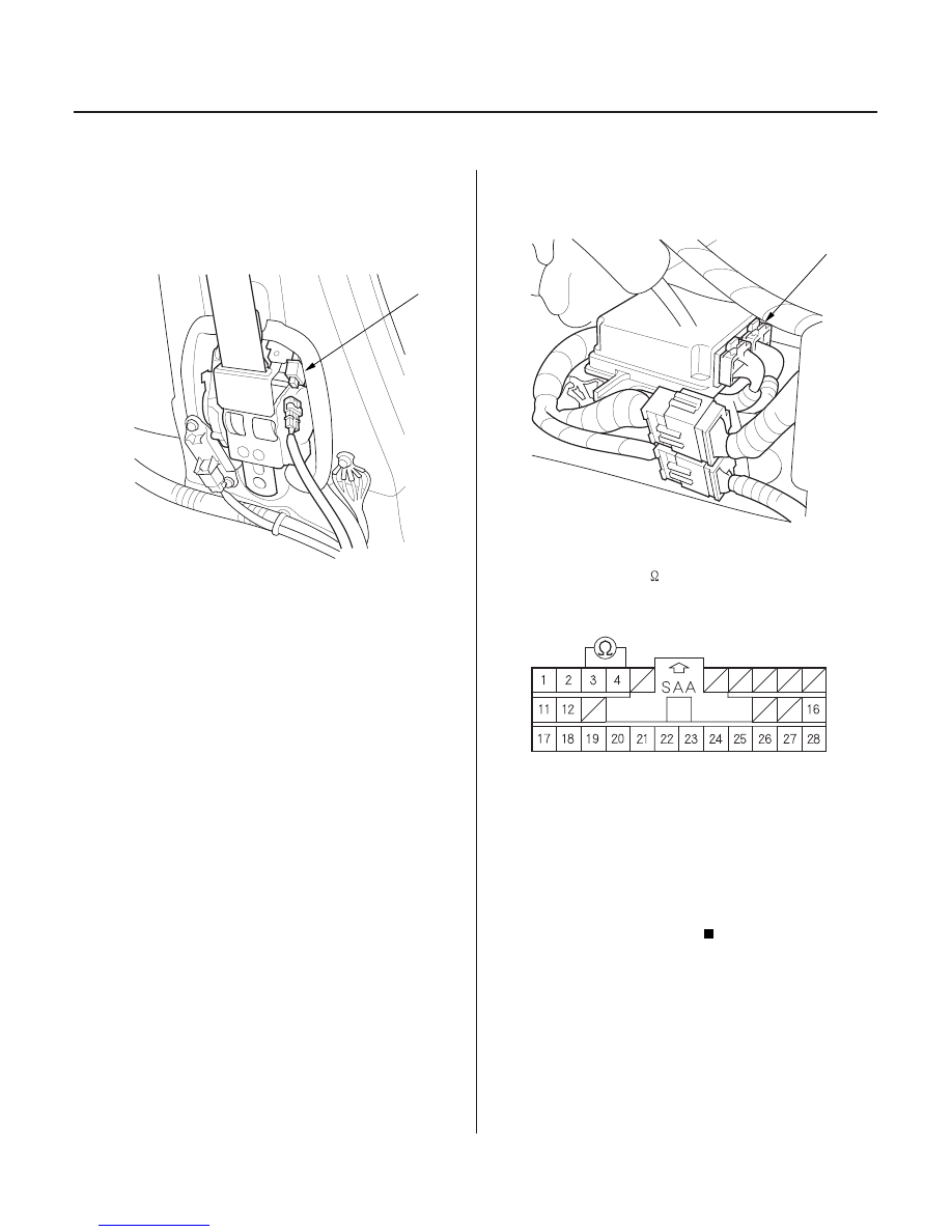
SRS UNIT CONNECTOR B (28P)
15. Turn the ignition switch OFF. Disconnect the
battery negative cable, and wait for 3 minutes.
16. Disconnect the driver’s seat belt tensioner
connector (A).
17. Disconnect SRS unit connector B (28P) from the
SRS unit. Do not disconnect the special tool from
the SRS main harness 2P connector.
18. Check resistance between the No. 3 and No. 4
terminals of SRS unit connector B (28P). There
should be 2.0
3.0
.
Faulty SRS unit or poor contact at SRS unit
connector B (28P) and the SRS unit. Check the
connection; if the connection is OK, replace the
SRS unit (see page 23-384).
Go to step 19.
Wire side of female terminals
Is the r esistance as specif ied?
03/07/29 10:38:04 61S0X050_230_0234