Honda Odyssey 2004. Manual - part 561


  Index      Honda     Honda Odyssey 2004 - service repair manual 2004 year


Search            


Content   ..  559  560  561  562   ..


Honda Odyssey 2004. Manual - part 561


01

02

03

S0X4AC5K79100081144FAAT00

’02 Model

DTC 14-4:

YES

NO

23-186

SRS

DTC Troubleshooting (cont’d)

A

A

B

A

B

Faulty Power Supply to the Front

Passenger’s Side Impact Sensor

1. Erase the DTC memory (see page 23-38).

2. Turn the ignition switch ON (II), and check that the

SRS indicator comes on for about 6 seconds and
then goes off.

Go to step 3.

Intermittent failure, system is OK at this time.

Go to Troubleshooting Intermittent Failures (see
page 23-39).

3. Turn the ignition switch OFF. Disconnect the

battery negative cable, and wait for 3 minutes.

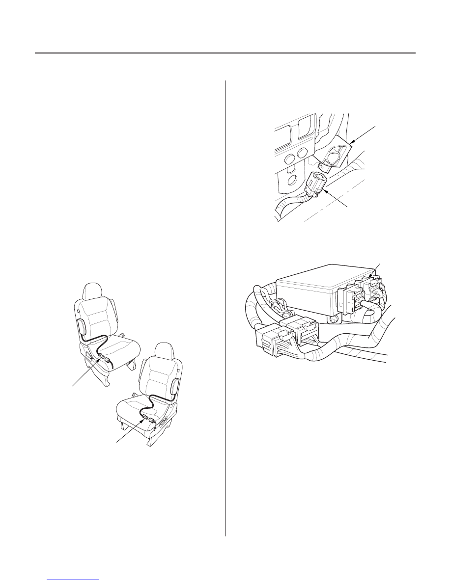
4. Disconnect the driver’s side airbag and front

passenger’s side airbag 2P connectors (A).

5. Disconnect the right side wire harness 2P

connector (A) from the front passenger’s side
impact sensor (B).

6. Disconnect SRS unit connector B (18P) from the

SRS unit.

Does the SRS indicator stay on?

03/07/29 10:36:28 61S0X050_230_0186

01

02

*01

03

YES

NO

YES

NO

YES

NO

23-187

SRS UNIT CONNECTOR B (18P)

SRS UNIT CONNECTOR B (18P)

C852

A

SRS FLOOR SUBHARNESS 28P CONNECTOR

7. Check resistance between the No. 9 terminal of

SRS unit connector B (18P) and body ground. There
should be an open circuit, or at least 1 M

.

Go to step 8.

Go to step 9.

8. Check resistance between the No. 9 and No. 16

terminals of SRS unit connector B (18P). There
should be an open circuit, or at least 1 M

.

Faulty front passenger’s side impact sensor

or SRS unit; replace the front passenger’s side
impact sensor (see page 23-385). If the problem is
still present, replace the SRS unit
(see page 23-382).

Go to step 11.

9. Disconnect the SRS floor subharness 28P

connector (A) from the SRS floor harness 28P
connector C852.

10. Check resistance between the No. 28 terminal of

the SRS floor subharness 28P connector and body
ground. There should be an open circuit, or at least
1 M

.

Short to ground in the SRS floor harness;

replace the SRS floor harness.

Short to ground in the SRS floor subharness

or right side wire harness; replace the faulty
harness.

(cont’d)

Wire side of female terminals

Wire side of female terminals

Wire side of female terminals

Is the r esistance as specif ied?

Is the r esistance as specif ied?

Is the r esistance as specif ied?

03/07/29 10:36:29 61S0X050_230_0187

*02

04

YES

NO

23-188

SRS

DTC Troubleshooting (cont’d)

C852

A

SRS FLOOR SUBHARNESS 28P CONNECTOR

11. Disconnect the SRS floor subharness 28P

connector (A) from the SRS floor harness 28P
connector C852.

12. Check resistance between the No. 28 and No. 27

terminals of the SRS floor subharness 28P
connector. There should be an open circuit, or at
least 1 M

.

Short in the SRS floor harness; replace the

SRS floor harness.

Short in the SRS floor subharness or right

side wire harness; replace the faulty harness.

Wire side of female terminals

Is the r esistance as specif ied?

03/07/29 10:36:30 61S0X050_230_0188

*01

02

S0X4AC5K79100081151FAAT00

’02 Model

DTC 15-1:

YES

NO

YES

NO

YES

NO

YES

NO

23-189

D

A

OPDS UNIT HARNESS CONNECTOR D (8P)

Faulty OPDS Unit or OPDS System

Not Initialized

NOTE:

• An incorrect OPDS unit can cause DTC 15-1.
• A new (uninitialized) OPDS unit installed with a faulty

OPDS sensor can also cause DTC 15-1.

• If you install a new OPDS unit and a new SRS unit at

the same time, initialize the OPDS manually (see
page 23-40), do not use the HDS.

1. Make sure nothing is on the front passenger’s seat.

2. Initialize the OPDS unit (see page 23-40).

3. Erase the DTC memory (see page 23-38).

4. Read the DTC (see page 23-35).

Go to step 5.

Intermittent failure, system is OK at this time.

Go to Troubleshooting Intermittent Failures (see
page 23-39).

5. Check the No. 11 (10A) fuse in the under-dash fuse/

relay box.

Go to step 6.

Go to step 9.

6. Disconnect OPDS unit harness 8P connector D (8P)

from the OPDS unit (A).

7. Turn the ignition switch ON (II).

8. Check for voltage between the No. 4 terminal of the

OPDS unit harness connector D (8P) and body
ground. There should be battery voltage.

Go to step 16.

Open in dashboard wire harness A or B, right

side harness, wire harness or OPDS unit harness;
replace the faulty harness.

9. Replace the No. 11 (10A) fuse in the under-dash

fuse/relay box.

10. Turn the ignition switch ON (II) for 30 seconds, then

turn it OFF.

11. Check the No. 11 (10A) fuse in under-dash fuse/

relay box.

Intermittent failure, system is OK at this time.

Go to Troubleshooting Intermittent Failures (see
page 23-39).

Go to step 12.

12. Replace the No. 11 (10A) fuse in the under-dash

fuse/relay box.

(cont’d)

Wire side of female terminals

Is DT C 15-1 indicated?

Is the f use OK ?

Is ther e batter y voltage?

Is the f use OK ?

03/07/29 10:36:30 61S0X050_230_0189


Content   ..  559  560  561  562   ..