Honda Odyssey 2004. Manual - part 531
*90
S0X4AZBH46400000000EAAT00
−
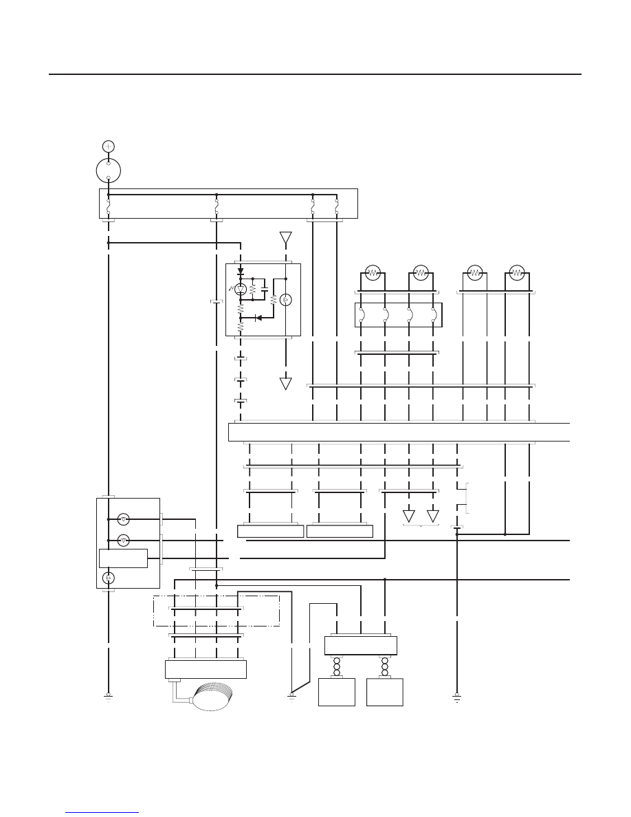
’03-04 Models
23-66
SRS
Circuit Diagram (cont’d)
C851
C205
C304
C402
C861
C589
C505
N
P
I
C852
C558
C501
C503
G851
BLK
13
24
YEL/GRN
YEL
6
3
5
BLU
BLK
YEL/GRN
BLU
RED/BLU
YEL/GRN
GRN
RED/BLK
YEL
C851
RED
2
3
1
4
3
9
3
4
C
A
GRN
BLU
YEL/GRN
23
BLK
BLK
22
BLK
2
1
BRN
GRY
BLU
5
4
6
26
23
24
25
BLU
GRY
BRN
LT GRN/BLK
25
LT GRN/BLK
26
BRN
24
GRY
BLU
19
C851
2
1
RIGHT FRONT IMPACT SENSOR
GRN
BRN
LEFT FRONT IMPACT SENSOR
1
2
RED
BRN/BLK
4
2
RED
BRN
BRN/BLK
GRN
28
GRN
A
*3
4
3
1
2
BLK
4
RED/BLU
4
RED/BLU
RED/BLU
1
6
20
RED/BLU
B
A
B
DRIVER’S UNDER DASH FUSE/RELAY BOX
28
27
11
12
4
2
BLK
RED/WHT
BLK/WHT
GRN
GRN/BLK
GRN/WHT
GRN/YEL
BLU/YEL
YEL
WHT
RED/YEL
2
1
8
7
3
4
10
9
17
18
BRN/BLK
18
17
RED/YEL
WHT
YEL
BLU/YEL
4
3
2
GRN/YEL
GRN/WHT
GRN/BLK
GRN
BLK/WHT
RED/WHT
GRN
BLU
WHT/RED
BLK
G581
4
3
1
BLK
BLK
7
8
YEL
YEL/GRN
2
1
7
4
No.1
(15A)
(10A)
No.2
No.11
(10A)
(10A)
No.9
IG1
BAT
3
4
9
10
2
1
4
3
2
1
BLK
BLK
1
2
BATTERY
11
GAUGE ASSEMBLY
16
8
4
3
7
OPDS UNIT
SRS UNIT
BRN
16
27
RED
2
1
3
4
BLK
YEL/GRN
BLU
GRN
15
G503
BLK
IGNITION
SWITCH
IG1 HOT in ON (II)
and START (III)
DASHBOARD
WIRE
HARNESS A
DASHBOARD
WIRE
HARNESS B
DASHBOARD
WIRE
HARNESS A
MULTIPLEX
CONTROL UNIT
PASSENGER
AIRBAG
CUTOFF
INDICATOR
DASHBOARD
WIRE
HARNESS A
LEFT SIDE
WIRE
HARNESS
SRS
FLOOR
SUB
HARNESS
SRS
FLOOR
HARNESS
SRS
MAIN
HARNESS
MULTIPLEX
CONTROL
UNIT
DRIVER’S
AIRBAG
FIRST
INFLATOR
DRIVER’S
AIRBAG
SECOND
INFLATOR
FRONT
PASSENGER’S
AIRBAG
FIRST
INFLATOR
FRONT
PASSENGER’S
AIRBAG
SECOND
INFLATOR
CABLE
REEL
SRS
FLOOR
HARNESS
SRS
MAIN
HARNESS
LEFT ENGINE
COMPARTMENT
WIRE HARNESS
RIGHT ENGINE
COMPARTMENT
WIRE HARNESS
MEMORY
ERASE
SIGNAL (MES)
CONNECTOR
(2P)
DATA LINK
CONNECTOR (16P)
DASHBOARD
WIRE
HARNESS A
SRS FLOOR
HARNESS
DASHBOARD
WIRE HARNESS A
RIGHT SIDE
WIRE HARNESS
SIDE AIRBAG
CUTOFF
INDICATOR
SEAT BELT
REMINDER
LIGHT
SRS INDICATOR
CIRCUIT
SRS
INDICATOR
RIGHT SIDE
WIRE HARNESS
FRONT PASSENGER’S
WEIGHT SENSOR UNIT
INNER SIDE
FRONT
PASSENGER’S
WEIGHT
SENSOR
OUTER SIDE
FRONT
PASSENGER’S
WEIGHT
SENSOR
OPDS
SENSOR
OPDS
UNIT
HARNESS
DASHBOARD
WIRE HARNESS A
PASSENGER’S
SEAT WIRE
HARNESS
A
B
C
03/07/29 10:32:53 61S0X050_230_0066