Honda Odyssey 2004. Manual - part 514
01
S0X4A82J36100063191KBAT01
01
S0X4A82J36100042521KDAT02
22-384
22-384
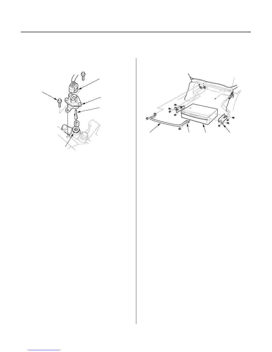
Navigation System
Vehicle Speed Pulse (VSP) Sensor
Replacement
Navigation Unit Removal/
Installation
A
C
B
E
D
A
D
C
B
1. Disconnect the 3P connector (A) from the vehicle
speed pulse (VSP) sensor (B).
2. Remove the mounting bolt (C), then remove the
VSP.
3. Install the VSP. Lubricate the new O-ring (D) and
the vehicle speed pulse (VSP) sensor joint (E) with
grease before installing.
1. Remove the navigation unit guard (A) from the
bracket.
2. Remove the navigation unit bracket (B) from the
passenger’s seat.
3. Remove the navigation unit (C) from the bracket.
4. Install the parts in the reverse order of removal.
NOTE: Install the navigation unit guard with the
arrow (D) pointing up.
03/07/29 10:28:52 61S0X050_220_0386