Honda Odyssey 2004. Manual - part 453


  Index      Honda     Honda Odyssey 2004 - service repair manual 2004 year


Search            


Content   ..  451  452  453  454   ..


Honda Odyssey 2004. Manual - part 453


01

S0X4A00J32323341903FCAT00

Driver’s Multiplex Control Unit

22-140

Entry Lights Control System

Control Unit Input Test

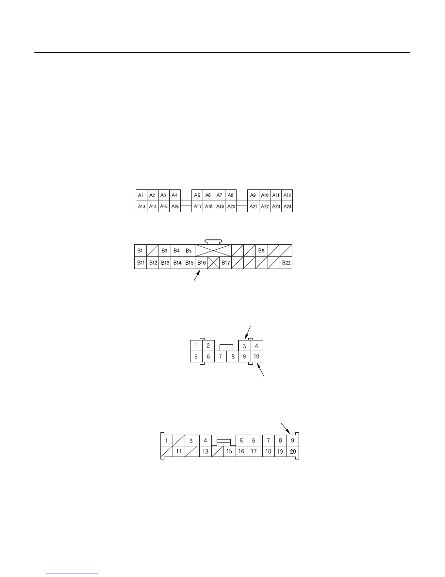
DRIVER’S UNDER-DASH FUSE/RELAY BOX SOCKET
(Driver’s multiplex control unit connector A)

DRIVER’S UNDER-DASH FUSE/RELAY BOX CONNECTOR A

DRIVER’S UNDER-DASH FUSE/RELAY BOX CONNECTOR O

BLU/WHT

GRN/YEL

GRN/ORN

DRIVER’S MULTIPLEX CONTROL UNIT CONNECTOR B

RED/GRN

1. Before testing the entry light control functions, troubleshoot the multiplex control system (see page 22-244).

2. Remove the driver’s multiplex control unit from the driver’s under-dash fuse/relay box.

3. Inspect the connector and socket terminals to be sure they are all making good contact.

• If the terminals are bent, loose or corroded, repair them as necessary, and recheck the system.
• If the terminals look OK, go to step 4.

Wire side of female terminals

Wire side of female terminals

Wire side of female terminals

03/07/29 10:21:31 61S0X050_220_0142

Cavity

Wire

Test condition

Test: Desired result

Cavity

Wire

Test condition

Test: Desired result

Possible cause if result is not obtained

Possible cause if result is not obtained

22-141

4. With the driver’s unit still disconnected, make these input tests at the connector and fuse/relay box socket.

• If any test indicates a problem, find and correct the cause, then recheck the system.
• If all the input tests prove OK, go to step 5.


A1

Fuse/relay

box socket

Under all
conditions

Attach to ground:
The ignition key light should
come on.

Blown No. 47 (20A) fuse in the
under-hood fuse/relay box
Blown LED
An open in the wire

A6

Combination
light switch
ON, jump
battery
voltage to B16
(RED/GRN)

Check for voltage to ground:
There should be battery voltage.

Blown No. 10 (15A) fuse in the
passenger’s under-dash fuse/
relay box
Faulty taillight relay
Faulty combination light switch
An open in the wire

A24

Ignition switch
ON (II)

Check for voltage to ground:
There should be battery voltage.

Blown No. 9 (10A) fuse in the
driver’s under-dash fuse/relay box
Faulty driver’s fuse/relay box

5. Reconnect the driver’s multiplex control unit to the fuse/relay box, and perform the following input tests at the

appropriate connectors on the back of the fuse/relay box.

• If any test indicates a problem, find and correct the cause, then recheck the system.
• If all the input tests prove OK, go to step 6.


O9

BLU/WHT

Ignition key is
in the ignition
switch

Check for voltage to ground:
There should be 1 V or less.

Poor ground (G401)
Faulty ignition switch
An open in the wire

Ignition key is
out of the
ignition switch

Check for voltage to ground:
There should be 5 V or more.

Faulty ignition switch
A short in the wire

A3

GRN/ORN

Driver’s door
open

Check for voltage to ground:
There should be 1 V or less.

Faulty driver’s door switch
An open in the wire

Driver’s door
closed

Check for voltage to ground:
There should be 5 V or more.

Faulty driver’s door switch
A short in the wire

A10

GRN/YEL

Left sliding
door open

Check for voltage to ground:
There should be 1 V or less.

Faulty left sliding door switch
An open in the wire

Left sliding
door closed

Check for voltage to ground:
There should be 5 V or more.

Faulty left sliding door switch
A short in the wire

(cont’d)

03/07/29 10:21:32 61S0X050_220_0143

*01

Passenger’s Multiplex Control Unit

22-142

Entry Lights Control System

Control Unit Input Test (cont’d)

PASSENGER’S UNDER-DASH FUSE/RELAY BOX SOCKET
(Passenger’s multiplex contorl unit connector A)

GRN/WHT

GRN

PASSENGER’S UNDER-DASH FUSE/RELAY BOX CONNECTOR A

6. Remove the passenger’s multiplex control unit from the passenger’s under-dash fuse/relay box, and disconnect

its connector.

7. Inspect the connector and socket terminals to be sure they are all making good contact.

• If the terminals are bent, loose or corroded, repair them as necessary, and recheck the system.
• If the terminals look OK, go to step 8.

Wire side of female terminals

03/07/29 10:21:32 61S0X050_220_0144

Cavity

Wire

Test condition

Test: Desired result

Cavity

Wire

Test condition

Test: Desired result

Possible cause if result is not obtained

Possible cause if result is not obtained

22-143

8. With the control unit still disconnected, make these input tests at the connector and fuse/relay box socket.

• If any test indicates a problem, find and correct the cause, then recheck the system.
• If all the input tests prove OK, go to step 9.


A22

Fuse/relay

box socket

Ignition switch
ON (II)

Check for voltage to ground:
There should be battery voltage.

Blown No. 9 (10A) fuse in the
driver’s under-dash fuse/relay box
An open in the wire

A21

Ceiling light
switches in the
middle (Door)
position

Attach to ground:
Ceiling lights should come on.

Blown No. 11 (10A) fuse in the
passenger’s under-dash fuse/
relay box
Blown No. 54 (40A) fuse in the
under-hood fuse/relay box
Faulty interior lights relay
Faulty interior lights switch
Faulty ceiling light bulb
Poor ground (G401)
An open in the wire

9. Reconnect the passenger’s multiplex control unit to the fuse/relay box, and perform the following input tests at

the appropriate connectors on the back of the fuse/relay box.

• If any test indicates a problem, find and correct the cause, then recheck the system.
• If all the input tests prove OK, go to step 10.


A16

GRN

Passenger’s
door open

Check for voltage to ground:
There should be 1 V or less.

Faulty front passenger’s door
switch
An open in the wire

Passenger’s
door closed

Check for voltage to ground:
There should be 5 V or more.

Faulty front passenger’s door
switch
A short to ground in the wire

A14

GRN/WHT

Right sliding
door open

Check for voltage to ground:
There should be 1 V or less.

Faulty right rear door switch
An open in the wire

Right sliding
door closed

Check for voltage to ground:
There should be 5 V or more.

Faulty right rear door switch
A short to ground in the wire

(cont’d)

03/07/29 10:21:32 61S0X050_220_0145


Content   ..  451  452  453  454   ..