Honda Odyssey 2004. Manual - part 394


  Index      Honda     Honda Odyssey 2004 - service repair manual 2004 year


Search            


Content   ..  392  393  394  395   ..


Honda Odyssey 2004. Manual - part 394


*01

22

23

02

S0X4A00G10110112011LAAT20

Special Tools Required

21-52

Heating/Air Conditioning

Compressor Clutch Overhaul

A
18 N·m (1.8 kgf·m, 13 lbf·ft)

B

A

B

A

B

A

B

C

A/C clutch holder, Robinair 10204 or Kent-Moore
J37872, or Honda Tool and Equipment KMT-J33939,
commercially available

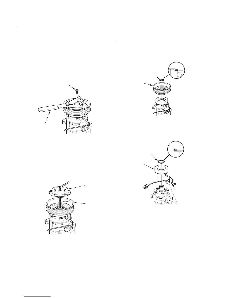
1. Remove the center bolt (A) while holding the

pressure plate with a commercially available A/C
clutch holder (B).

2. Remove the pressure plate (A) and shim(s) (B),

taking care not to lose the shim(s). If the clutch
needs adjustment, increase or decrease the
number and thickness of shims as necessary, then
reinstall the pressure plate, and recheck its
clearance (see page 21-51).

NOTE: The shims are available in four thicknesses:
0.1 mm, 0.3 mm, 0.5 mm, and 1.5 mm.

3. If you are replacing the field coil, remove the snap

ring (A) with snap ring pliers, then remove the
pulley (B). Be careful not to damage the pulley or
the compressor.

4. Remove the screw from the field coil ground

terminal (A). Remove the snap ring (B) with snap
ring pliers, then remove the field coil (C). Be careful
not to damage the field coil or the compressor.

03/07/29 10:11:17 61S0X050_210_0053

21

S0X4A00G10110112021KBAT20

21-53

21-53

Compressor Relief Valve
Replacement

A
13.2 N·m (1.35 kgf·m, 9.76 lbf·ft)

B

5. Reassemble the clutch in the reverse order of

disassembly, and note these items:

• Install the field coil with the wire side facing

down, and align the boss on the field coil with the
hole in the compressor.

• Clean the pulley and compressor sliding surfaces

with contact cleaner or other non-petroleum
solvent.

• Install new snap rings, note the installation

direction, and make sure they are fully seated in
the groove.

• Make sure that the pulley turns smoothly after it’s

reassembled.

• Route and clamp the wires properly or they can

be damaged by the rotor pulley.

1. Recover the refrigerant with a recovery/recycling/

charging station (see page 21-56).

2. Remove the relief valve (A) and the O-ring (B). Plug

the opening to keep foreign matter from entering
the system and the compressor oil from running
out.

3. Clean the mating surfaces.

4. Replace the O-ring with a new one at the relief

valve, and apply a thin coat of refrigerant oil before
installing it.

5. Remove the plug, and install and tighten the relief

valve.

6. Charge the system (see page 21-58).

03/07/29 10:11:17 61S0X050_210_0054

21

22

23

S0X4A00G10110200000KBAT20

21-54

Heating/Air Conditioning

Condenser Replacement

6 x 1.0 mm
9.8 N·m (1.0 kgf·m,
7.2 lbf·ft)

6 x 1.0 mm
9.8 N·m
(1.0 kgf·m, 7.2 lbf·ft)

A

B

6 x 1.0 mm
9.8 N·m (1.0 kgf·m, 7.2 lbf·ft)

1. Recover the refrigerant with a recovery/recycling/

charging station (see page 21-56).

2. Remove the front grille (see page 20-142) and the

hood latch (see page 20-154).

3. Remove the bolts and the radiator upper brackets.

4. Remove the bolts, then disconnect the discharge

line (A) and receiver line (B) from the condenser.
Plug or cap the lines immediately after
disconnecting them to avoid moisture and dust
contamination.

5. Remove the bolts, then remove the condenser by

lifting it up. Be careful not to damage the radiator
or the condenser fins when removing the
condenser.

6. Install the condenser in the reverse order of

removal, and note these items:

• If you’re installing a new condenser, add

refrigerant oil (DENSO ND-OIL 8) (see page 21-6).

• Replace the O-rings with new ones at each fitting,

and apply a thin coat of refrigerant oil before
installing them. Be sure to use the correct O-rings
for HFC-134a (R-134a) to avoid leakage.

• Immediately after using the oil, reinstall the cap

on the container, and seal it to avoid moisture
absorption.

• Do not spill the refrigerant oil on the vehicle; it

may damage the paint. If the refrigerant oil
contacts the paint, wash it off immediately.

• Be careful not to damage the radiator or the

condenser fins when installing the condenser.

• Charge the system (see page 21-58).

03/07/29 10:11:18 61S0X050_210_0055

11

S0X4A00G10100050552KBAT70

21-55

Receiver/Dryer Desiccant Replacement

D

B

C

A

1. Remove the condensor (see page 21-54).

2. Remove the cap (A) from the bottom of the

condenser, then remove the O-rings (B), the filter
(C) and the desiccant (D).

3. Install the desiccant in the reverse order of removal.

Replace the O-rings with new ones, and apply a
thin coat of refrigarent oil (DENSO ND-OIL 8) before
installing them. Be sure to use the correct O-rings
for HFC-134a (R-134a) to avoid leakage.

03/07/29 10:11:18 61S0X050_210_0056


Content   ..  392  393  394  395   ..