Honda Odyssey 2004. Manual - part 389


  Index      Honda     Honda Odyssey 2004 - service repair manual 2004 year


Search            


Content   ..  387  388  389  390   ..


Honda Odyssey 2004. Manual - part 389


*01

21

S0X4A00G10110112012FAAT20

YES

NO

YES

NO

YES

NO

YES

NO

YES

NO

21-32

Heating/Air Conditioning

Compressor Clutch Circuit Troubleshooting

COMPRESSOR CLUTCH RELAY 4P SOCKET

COMPRESSOR CLUTCH RELAY 4P SOCKET

JUMPER
WIRE

RED

NOTE:

• Do not use this troubleshooting procedure if the fans

are also inoperative with the A/C on. Refer to the
symptom troubleshooting index.

• Before performing symptom troubleshooting, check

for powertrain DTCs (see page 11-3).

1. Check the No. 59 (7.5A) fuse in the under-hood fuse

/relay box, and the No. 3 (7.5A) fuse in the driver’s
under-dash fuse/relay box.

Go to step 2.

Replace the fuse(s), and recheck.

2. Check the engine coolant temperature, throttle

position, and idle speed (Use the HDS PGM-FI data
list if possible).

Sensor

’99-01 models:

163

194°F

(73

90°C)

’02-04 models:

169

194°F

(76

90°C)

TPS

About 0.5 V

RPM

More than 730

Go to step 3.

Troubleshoot and repair cause of high engine

coolant temperature, low idle, or excessively high
throttle position sensor reading.

3. Remove the compressor clutch relay from the

under-hood fuse/relay box, and test it (see page 22-
88).

Go to step 4.

Replace the compressor clutch relay.

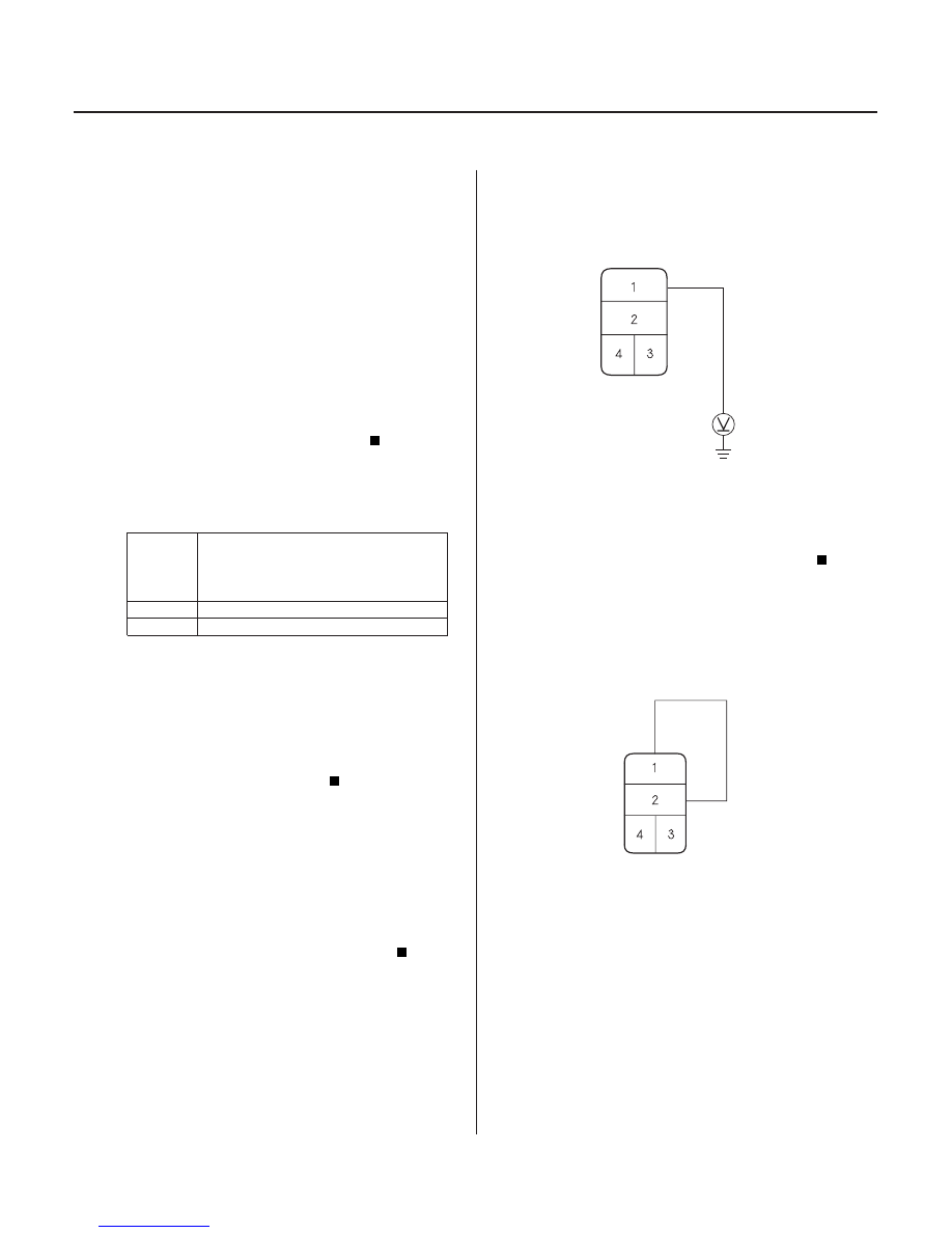
4. Measure the voltage between the No.1 terminal of

the compressor clutch relay 4P socket and body
ground.

Go to step 5.

Replace the under-hood fuse/relay box.

5. Connect the No. 1 and No. 2 terminals of the

compressor clutch relay 4P socket with a jumper
wire.

Go to step 6.

Go to step 15.

6. Disconnect the jumper wire.

7. Turn the ignition switch ON (II).

Ar e the f uses OK ?

Is the coolant temper atur e, thr ottle position, and
idle speed OK ?

Is the r elay OK ?

Is ther e batter y voltage?

Does the compr essor clutch click ?

03/07/29 10:10:30 61S0X050_210_0033

22

*02

*03

YES

NO

’99-00 and ’02-04 models:

’01 model:

YES

NO

21-33

COMPRESSOR CLUTCH RELAY 4P SOCKET

BLK/YEL

PCM CONNECTOR A (32P)

RED

PCM CONNECTOR E (31P)

RED

8. Measure the voltage between the No. 4 terminal of

the compressor clutch relay 4P socket and body
ground.

Go to step 9.

Repair open in the wire between the No. 3

fuse in the driver’s under-dash fuse/relay box and
the compressor clutch relay.

9. Turn the ignition switch OFF.

10. Reinstall the compressor clutch relay.

11. Make sure the A/C switch is OFF.

12. Turn the ignition switch ON (II).

13. ’99-00 and ’02-04 models: Using the Backprobe Set,

measure the voltage between the No. 17 terminal
of PCM connector A (32P) and body ground with
the PCM connectors connected.
’01 model: Using the Backprobe Set, measure the
voltage between the No. 12 terminal of PCM
connector E (31P) and body ground with the PCM
connector connected.

Go to step 14.

Repair open in the wire between the

compressor clutch relay and the PCM.

(cont’d)

Wire side of female terminals

Wire side of female terminals

Is ther e batter y voltage?

Is ther e batter y voltage?

03/07/29 10:10:31 61S0X050_210_0034

*04

*05

*06

’99-00 and ’02-04 models:

’01 model:

YES

NO

YES

NO

21-34

Heating/Air Conditioning

Compressor Clutch Circuit Troubleshooting (cont’d)

PCM CONNECTOR A (32P)

BLU/RED

PCM CONNECTOR E (31P)

BLU/RED

COMPRESSOR CLUTCH RELAY 4P SOCKET

RED

RED

COMPRESSOR CLUTCH 1P CONNECTOR

14. ’99-00 and ’02-04 models: Using the Backprobe Set,

measure the voltage between the No. 27 terminal
of PCM connector A (32P) and body ground with
the PCM connectors connected.
’01 model: Using the Backprobe Set, measure the
voltage between the No. 21 terminal of PCM
connector E (31P) and body ground with the PCM
connector connected.

Check for loose wires or poor connections at

PCM connector A (32P) or E (31P). If the
connections are good, substitute a known-good
PCM, and recheck. If the symptom/indication goes
away, replace the original PCM.

Repair open in the wire between the PCM and

the A/C pressure switch.

15. Disconnect the jumper wire.

16. Disconnect the compressor clutch 1P connector.

17. Check for continuity between the No. 2 terminal of

the compressor clutch relay 4P socket and the No. 1
terminal of the compressor clutch 1P connector.

Check the compressor clutch clearance and

the compressor clutch field coil (see page 21-51).
Repair as needed.

Repair open in the wire between the

compressor clutch relay and the compressor
clutch.

Wire side of female terminals

Wire side of female terminals

Terminal side of male terminals

Is ther e batter y voltage?

Is ther e continuity?

03/07/29 10:10:31 61S0X050_210_0035

*01

02

*02

S0X4A11G10100012062FAAT20

YES

NO

YES

NO

YES

NO

21-35

A/C Pressure Switch Circuit Troubleshooting

A/C PRESSURE SWITCH 4P CONNECTOR

BLU/RED

A/C PRESSURE SWITCH

HEATER CONTROL PANEL 22P CONNECTOR

RED/WHT

NOTE:

• Do not use this troubleshooting procedure if any of

the following items are operative; condenser fan,
radiator fan, A/C compressor, or if the heater is
inoperative. Refer to the symptom troubleshooting
index.

• Before performing symptom troubleshooting, check

for powertrain DTCs (see page 11-3).

1. Disconnect the A/C pressure switch 4P connector.

2. Turn the ignition switch ON (II).

3. Measure the voltage between the No. 1 terminal of

the A/C pressure switch 4P connector and body
ground.

Go to step 4.

Repair open in the wire between A/C diode A,

the PCM and the A/C pressure switch.

4. Turn the ignition switch OFF.

5. Check for continuity between the No. 1 and No. 4

terminals of the A/C pressure switch.

Go to step 6.

Go to step 16.

6. Reconnect the A/C pressure switch 4P connector.

7. Disconnect the heater control panel 22P connector.

8. Turn the ignition switch ON (II).

9. Measure the voltage between the No. 5 terminal of

the heater control panel 22P connector and body
ground.

Go to step 10.

Repair open in the wire between the heater

control panel and the A/C pressure switch.

10. Turn the ignition switch OFF.

(cont’d)

Wire side of female terminals

Wire side of female terminals

Is ther e batter y voltage?

Is ther e continuity?

Is ther e batter y voltage?

03/07/29 10:10:32 61S0X050_210_0036


Content   ..  387  388  389  390   ..