Honda Odyssey 2004. Manual - part 388


  Index      Honda     Honda Odyssey 2004 - service repair manual 2004 year


Search            


Content   ..  386  387  388  389   ..


Honda Odyssey 2004. Manual - part 388


02

04

*02

*03

YES

NO

YES

NO

YES

NO

21-28

Heating/Air Conditioning

Radiator and Condenser Fan Low Speed Circuit Troubleshooting (cont’d)
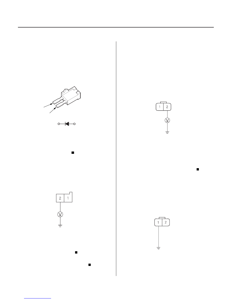
A/C DIODE A

1

2

1

2

A/C DIODE A 2P SOCKET

GRN

CONDENSER FAN 2P CONNECTOR

BLU/YEL

CONDENSER FAN 2P CONNECTOR

BLU/RED

JUMPER
WIRE

8. Reinstall the condenser fan relay.

9. Remove A/C diode A from the passenger’s under-

dash fuse/relay box.

10. Check for current flow in both directions between

the No. 1 and No. 2 terminals of A/C diode A.

Go to step 11.

Replace A/C diode A.

11. Turn the ignition switch ON (II).

12. Measure the voltage between the No. 2 terminal of

A/C diode A 2P socket and body ground.

Repair open in the wire between A/C diode A

and the A/C pressure switch.

Repair open in the wire between the

condenser fan relay and A/C diode A.

13. Disconnect the jumper wire.

14. Reinstall the condenser fan relay.

15. Disconnect the condenser fan 2P connector.

16. Turn the ignition switch ON (II), then turn the A/C

and fan switches ON.

17. Measure the voltage between the No. 2 terminal of

the condenser fan 2P connector and body ground.

Go to step 18.

Repair open in the wire between the

condenser fan relay and the condenser fan.

18. Turn the A/C and fan switches OFF, then turn the

ignition switch OFF.

19. Reconnect the condenser fan 2P connector.

20. Connect the No.1 terminal of the condenser fan 2P

connector to body ground with jumper wire.

Wire side of female terminals

Wire side of female terminals

Is ther e cur r ent f low in only one dir ection?

Is ther e batter y voltage?

Is ther e batter y voltage?

03/07/29 10:10:27 61S0X050_210_0029

07

*05

*04

YES

NO

YES

NO

YES

NO

YES

NO

YES

NO

21-29

FAN CONTROL RELAY 5P SOCKET

BLU/RED

FAN CONTROL RELAY 5P SOCKET

RADIATOR FAN 2P CONNECTOR

BLU/BLK

BLU/BLK

RADIATOR FAN 2P CONNECTOR

BLK

21. Turn the ignition switch ON (II), then turn the A/C

and fan switches ON.

Go to step 22.

Replace the condenser fan motor.

22. Turn the A/C and fan switches OFF, then turn the

ignition switch OFF.

23. Disconnect the jumper wire.

24. Remove the fan control relay from the ABS relay

box, and test it (see page 22-88).

Go to step 25.

Replace the fan control relay.

25. Turn the ignition switch ON (II), then turn the A/C

and fan switches ON.

26. Measure the voltage between the No. 1 terminal of

the fan control relay 5P socket and body ground.

Go to step 27.

Repair open in the wire between the

condenser fan and the fan control relay.

27. Turn the A/C and fan switches OFF, then turn the

ignition switch OFF.

28. Disconnect the radiator fan 2P connector.

29. Check for continuity between the No. 4 terminal of

the fan control relay 5P socket and the No. 2
terminal of the radiator fan 2P connector.

Go to step 30.

Repair open in the wire between the fan

control relay and the radiator fan.

30. Check for continuity between the No. 1 terminal of

the radiator fan 2P connector and body ground.

Replace the radiator fan motor.

Check for an open in the wire between the

radiator fan and body ground. If the wire is OK,
check for poor ground at G201.

Wire side of female terminals

Wire side of female terminals

Does the condenser f an r un?

Is the r elay OK ?

Is ther e batter y voltage?

Is ther e continuity?

Is ther e continuity?

03/07/29 10:10:28 61S0X050_210_0030

01

02

S0X4A00G10110212033FAAT00

YES

NO

YES

NO

YES

NO

YES

NO

21-30

Heating/Air Conditioning

Condenser Fan High Speed Circuit Troubleshooting

FAN CONTROL RELAY 5P SOCKET

BLK/YEL

BLK

FAN CONTROL RELAY 5P SOCKET

NOTE:

• Do not use this troubleshooting procedure if the

radiator fan and/or the compressor is inoperative.
Refer to the symptom troubleshooting index.

• Before performing symptom troubleshooting, check

for powertrain DTCs (see page 11-3).

1. Check the No. 3 (7.5A) fuse in the driver’s under-

dash fuse/relay box.

Go to step 2.

Replace the fuse, and recheck.

2. Remove the fan control relay from the ABS relay

box, and test it (see page 22-88).

Go to step 3.

Replace the fan control relay.

3. Turn the ignition switch ON (II).

4. Measure the voltage between the No. 5 terminal of

the fan control relay 5P socket and body ground.

Go to step 5.

Repair open in the wire between the No. 3

fuse in the driver’s under-dash fuse/relay box and
the fan control relay.

5. Turn the ignition switch OFF.

6. Check for continuity between the No. 2 terminal of

the fan control relay 5P socket and body ground.

Repair open in the wire between the fan

control relay and the radiator fan relay.

Check for an open in the wire between the fan

control relay and body ground. If the wire is OK,
check for poor ground at G201.

Is the f use OK ?

Is the r elay OK ?

Is ther e batter y voltage?

Is ther e continuity?

03/07/29 10:10:28 61S0X050_210_0031

01

*01

*02

*03

S0X4A00G10110249111FAAT00

YES

NO

YES

NO

YES

NO

YES

NO

21-31

Radiator and Condenser Fan High Speed Circuit Troubleshooting

A/C DIODE C

1

2

1

2

BLU/RED

A/C DIODE C 2P SOCKET

GRN/YEL

A/C PRESSURE SWITCH 4P CONNECTOR

A/C PRESSURE SWITCH 4P CONNECTOR

BLU/RED

BLU/RED

NOTE:

• Do not use this troubleshooting procedure if only one

fan is inoperative, or if the compressor is inoperative.
Refer to the symptom troubleshooting index.

• Before performing symptom troubleshooting, check

for powertrain DTCs (see page 11-3).

1. Remove A/C diode C from the right side of dash.

2. Check for current flow in both directions between

the No. 1 and No. 2 terminals of A/C diode C.

Go to step 3.

Replace A/C diode C.

3. Turn the ignition switch ON (II).

4. Measure the voltage between the No. 2 terminal of

A/C diode C 2P socket and body ground.

Go to step 5.

Repair open in the wire between the radiator

fan relay and A/C diode C.

5. Turn the ignition switch OFF.

6. Reinstall A/C diode C.

7. Disconnect the A/C pressure switch 4P connector.

8. Turn the ignition switch ON (II).

9. Measure the voltage between the No. 2 terminal of

the A/C pressure switch 4P connector and body
ground.

Go to step 10.

Repair open in the wire between A/C diode C

and the A/C pressure switch.

10. Turn the ignition switch OFF

11. Check for continuity between the No. 1 and No. 3

terminals of the A/C pressure switch 4P connector.

Replace the A/C pressure switch.

Repair open in the wire between the A/C

pressure switches A and B.

Wire side of female terminals

Wire side of female terminals

Wire side of female terminals

Is ther e cur r ent f low in only one dir ection?

Is ther e batter y voltage?

Is ther e batter y voltage?

Is ther e continuity?

03/07/29 10:10:29 61S0X050_210_0032


Content   ..  386  387  388  389   ..