Honda Odyssey 2004. Manual - part 345


  Index      Honda     Honda Odyssey 2004 - service repair manual 2004 year


Search            


Content   ..  343  344  345  346   ..


Honda Odyssey 2004. Manual - part 345


01

01

S0X4A00J16170920071KBAT00

20-22

Doors

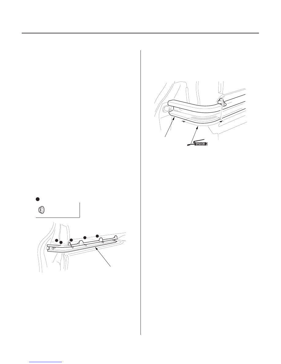
Sliding Door Center Rail Replacement

Fastener Locations

: Nut, 5

6 x 1.0 mm
9.8 N·m
(1.0 kgf·m,
7.2 lbf·ft)

A

A

NOTE: Take care not to scratch the center rail and body.

1. Remove these items:

• Sliding door (see page 20-25)
• Rear side trim panel (see page 20-60)

2. If equipped, pull and turn the adjusting pulley of the

power sliding door motor unit clockwise to
unfasten the power sliding door motor unit cable
(see step 5 on page 20-19).

3. Remove the center roller from the center rail.

4. If equipped, disconnect the power sliding door

motor unit cable from the center roller (see step 7
on page 20-19). Take care not to bend the cable.

5. If equipped, remove the bolts and nuts securing the

power sliding door motor unit (see step 10 on page
20-20), then move the unit as necessary.

6. Remove the nuts securing the center rail (A) from

inside of the vehicle, then remove the center rail.

NOTE: Take care not to drop the nuts inside the
body.

7. Install the center rail in the reverse order of

removal. Clean the groove portion of the center rail
(A) and if equipped with power sliding door, apply
multipurpose grease to the corner portion of the
sliding door, as shown.

03/07/29 10:00:11 61S0X050_200_0024

01

32

01

S0X4A00J54400020371MBAT30

20-23

Front Door Glass Adjustment

C

A

B
6 x 1.0 mm
9.8 N·m (1.0 kgf·m, 7.2 lbf·ft)

B

A

12 mm (1/2 in.)

0.5 m (18 in.)

300 mm (12 in.)

B

A

NOTE:

• Check the weatherstrips and glass run channel for

damage or deterioration, and replace them if
necessary.

• Wipe the run channel clean with a shop towel.
• Lubricate the run channel with Shin-Etsu grease

P/N 08798-9013.

1. Place the vehicle on a firm, level surface.

2. Remove these items:

• Door panel (see page 20-7)
• Pull pocket bracket (see page 20-2)
• Power window control unit bracket, ’03-04

models driver’s door (see page 20-2)

• Plastic cover (see page 20-2)

3. Carefully lower the glass (A) until you can see the

glass mounting bolts (B), then loosen them.

4. Push the glass (A) against the center channel (C),

then tighten the glass mounting bolts.

5. Check that the glass moves smoothly.

6. Raise the glass fully, and check for gaps. Check that

the glass (A) contacts the glass run channel (B)
evenly.

7. Check for water leaks. Run water over the roof and

on the sealing area as shown, and note these items:

• Use a 12 mm (1/2 in.) diameter hose (A).
• Adjust the rate of water flow as shown (B).
• Do not use a nozzle.
• Hold the hose about 300 mm (12 in.) away from

the door.

8. Attach the plastic cover, and install the door panel

(see page 20-7).

9. Test-drive and check for wind noise.

03/07/29 10:00:11 61S0X050_200_0025

*01

22

23

S0X4A00J16126700000MBAT20

20-24

Doors

Front Door Position Adjustment

A

D

C

F

D
8 x 1.25 mm
29 N·m
(3.0 kgf·m,
22 lbf·ft)

G
8 x 1.25 mm
29 N·m
(3.0 kgf·m,
22 lbf·ft)

D
8 x 1.25 mm
29 N·m
(3.0 kgf·m,
22 lbf·ft)

F

A

G
8 x 1.25 mm
29 N·m (3.0 kgf·m,
22 lbf·ft)

A

E
8 x 1.25 mm
29 N·m (3.0 kgf·m, 22 lbf·ft)

A

A

NOTE: Check for a flush fit with the body, then check for
equal gaps between the front, rear, and bottom door
edges and the body. Check that the door and body
edges are parallel.

1. Place the vehicle on a firm, level surface when

adjusting the doors.

2.

with a shop towel (C).

• Loosen the door mounting bolts (D), and move

the door up or down as necessary to equalize the
gaps, and in or out until it’s flush with the body.

3. If necessary, replace the hinge mounting bolt (E)

with the adjusting bolt (P/N 90101-SZ3-000) made
specifically for door adjustment, then adjust at the
hinges (F):

Loosen the hinge mounting bolts (E, G) slightly,
and move the door backward or forward, up or
down as necessary to equalize the gaps.

4. Check that the door and body edges are parallel. If

necessary, adjust the door cushions (A) to make the
rear of the door flush with the body.

5. Apply multipurpose grease to the pivot portions of

the hinges indicated by the arrows.

6. Apply touch-up paint to the hinge mounting bolts,

and around the hinges.

7. Check for water leaks (see step 7 on page 20-23).

8. Test-drive and check for wind noise.

03/07/29 10:00:12 61S0X050_200_0026

Support the door with a jack (B) that is padded

Adjust the door (A):

21

S0X4A00J16126721701MBAT01

01

S0X4A00J16170900000KDAT02

20-25

20-25

Front Door Striker Adjustment

Sliding Door Removal/Installation

B
8 x 1.25 mm
18 N·m (1.8 kgf·m, 13 lbf·ft)

A

C

D

Fasterner Location

: Bolt, 1

6 x 1.0 mm
8 N·m
(0.8 kgf·m,
6 lbf·ft)

A

Make sure the door latches securely without slamming
it. If necessary, adjust the striker (A): The striker nuts
are fixed, but the striker can be adjusted slightly up or
down, and in or out.

1. Loosen the screws (B), then insert a shop towel (C)

between the body and striker.

2. Lightly tighten the screws.

3. Wrap the striker with a shop towel, then adjust the

striker by tapping it with a plastic hammer (D). Do
not tap the striker too hard.

4. Loosen the screws, and remove the shop towel.

5. Lightly tighten the screws.

6. Hold the outer handle out, and push the door

against the body to be sure the striker allows a
flush fit. If the door latches properly, tighten the
screws and recheck.

NOTE:

• Have an assistant help you when removing and

installing the door.

• Use seat covers to avoid damaging any surfaces.
• Take care not to scratch the center rail and body.
• Take care not to drop and damage the door.
• Put on gloves to protect your hands.

1. Place the vehicle on a firm, level surface when

removing and installing the door.

2. Remove the sliding door sill trim (see page 20-58).

3. Remove the bolt, and remove the lower roller plate

(A) (manual sliding door) or stop spring (A) (power
sliding door).

4. Pull the sliding door backward fully.

(cont’d)

03/07/29 10:00:13 61S0X050_200_0027


Content   ..  343  344  345  346   ..