Honda Odyssey 2004. Manual - part 269


  Index      Honda     Honda Odyssey 2004 - service repair manual 2004 year


Search            


Content   ..  267  268  269  270   ..


Honda Odyssey 2004. Manual - part 269


*04

*05

*06

*07

Standard:

0.015

0.045 mm (0.0006

0.0018 in.)

14-470

Transmission End Cover

End Cover, 3rd Gear, Idler Gear, and 3rd Clutch Installation (cont’d)

A

B

A

07736-A01000B or
07736-A01000A

A

B

07GAB-PF50101 or
07GAB-PF50100

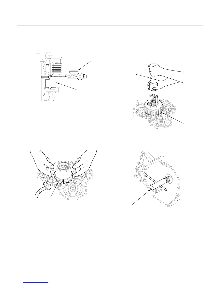
6. Set the dial indicator (A) to the countershaft 3rd

gear (B).

7. Measure the countershaft 3rd gear axial clearance

in at least three places, while moving the
countershaft 3rd gear (A).
Use the average as the actual clearance.

If the clearance is out of standard, select the
appropriate 31 x 63.5 mm splined washer in step
16.

8. Remove the locknut and conical spring washer.

9. Remove the 3rd clutch assembly (A) with the

special tool and a commercially available 3/8-16’’
slide hammer (B).

10. Remove the parts that were installed in step 5.

11. Install the special tool onto the mainshaft.

03/07/29 09:46:21 61S0X050_140_0473

*08

*09

*10

SPLINED WASHER, 31 x 63.5 mm

Mark

Part Number

Difference

14-471

F

H

E

D

A

B

C

G

J

I

H

G

E

D

C

B

A

F

12. Lubricate the following parts with ATF:

• Splines of the mainshaft 3rd gear and secondary

shaft idler gear.

• Threads of the mainshaft and secondary shaft.
• Threads of the old mainshaft and secondary shaft

locknuts.

• Old conical spring washer.

13. Install the mainshaft 3rd gear (A) and the old

conical spring washer (B) on the mainshaft (C).
Tighten the old locknut (D) to seat the 3rd gear to
226 N·m (23.0 kgf·m, 166 lbf·ft).

NOTE: Use a torque wrench to tighten the locknut.
Do not use an impact wrench.

14. Install the secondary shaft idler gear (E) and the old

conical spring washer (F) on the secondary shaft
(G). Tighten the old locknut (H) to seat the
secondary shaft idler gear to 226 N·m (23.0 kgf·m,
166 lbf·ft).

NOTE:

• Use a torque wrench to tighten the locknut. Do

not use an impact wrench.

• Secondary shaft locknut has left-hand threads.

15. Remove the old locknuts and old conical spring

washers from the mainshaft and secondary shaft.

16. If the 3rd gear axial clearance is out of standard

(measured in step 7), measure the difference of the
31 x 63.5 mm splined washer, and select the
appropriate splined washer from the table.

A

90520-P7W-000

3.503 mm (0.1379 in.)

B

90521-P7W-000

3.490 mm (0.1374 in.)

C

90522-P7W-000

3.477 mm (0.1369 in.)

D

90523-P7W-000

3.464 mm (0.1364 in.)

17. Install the thrust needle bearing (A), needle bearing

(B), 3rd gear (C), thrust needle bearing (D), and 31 x
63.5 mm splined washer (E) on the countershaft (F).

18. Wrap the shaft splines with tape to prevent O-ring

damage, then install new O-rings (G).

19. Remove the tape, then install the 3rd clutch

assembly (H), and old conical spring washer (I).
Tighten the old locknut (J) to 226 N·m (23.0 kgf·m,
166 lbf·ft).

NOTE: Use a torque wrench to tighten the locknut.
Do not use an impact wrench.

(cont’d)

03/07/29 09:46:22 61S0X050_140_0474

*11

*12

*13

14-472

Transmission End Cover

End Cover, 3rd Gear, Idler Gear, and 3rd Clutch Installation (cont’d)

A

A

A

B

B

B

E
6 x 1.0 mm
14 N·m (1.4 kgf·m, 10 lbf·ft)

F

D

A

B

C

20. Remove the old locknut and old conical spring

washer from the countershaft.

21. Lubricate the threads of each shaft, the new

locknuts, and new conical spring washers with ATF.

22. Install the new conical spring washers (A) in the

direction shown, and install the new locknuts (B).

23. Tighten the locknuts to 167 N·m (17.0 kgf·m,

123 lbf·ft).

NOTE:

• Use a torque wrench to tighten the locknuts. Do

not use an impact wrench.

• Countershaft and secondary shaft locknuts have

left-hand threads.

24. Remove the special tool from the mainshaft.

25. Stake each locknut into its shaft using 3.5 mm

punch.

26. Set the park lever in P position, then verify that the

park pawl (A) engages the park gear (B).

27. If the park pawl does not engage fully, check the

distance between the pawl shaft (C) and the park
lever roller pin (D) (see page 14-420).

28. Tighten the lock bolt (E), and bend the lock tab of

the lock washer (F) against the lock bolt head.

03/07/29 09:46:23 61S0X050_140_0475

*14

02

14-473

6 x 1.0 mm
12 N·m
(1.2 kgf·m,
8.7 lbf·ft)

6 x 1.0 mm
12 N·m
(1.2 kgf·m,
8.7 lbf·ft)

A

D

E

B

C

F

G

B

C

6 x 1.0 mm
12 N·m
(1.2 kgf·m, 8.7 lbf·ft)

C

A

B

G

J

K

H

I

D

F

E

6 x 1.0 mm
12 N·m
(1.2 kgf·m,
8.7 lbf·ft)

6 x 1.0 mm
12 N·m (1.2 kgf·m, 8.7 lbf·ft)

29. Install the new gasket (A) on the transmission

housing, and install the two dowel pins (B) and new
O-rings (C) over the top of the ATF feed pipes.

30. Install the end cover (D), and install the 13 bolts,

connector bracket (E) and harness clamp bracket (F).

31. Tighten the bolts in two or more steps in a

crisscross pattern.

32. Install the new O-ring on the input shaft (mainshaft)

speed sensor, then install it in the end cover.

33. Install the 8 x 12 mm ATF feed pipe (A) with its filter

side into the transmission housing.

34. Install the new gasket (B) in the mounting groove of

the A/T clutch pressure control solenoid valve C
body (C) properly, then install them on the
transmission housing. Do not pinch the gasket.

35. Install the ATF dipstick guide pipe (D) with the new

O-ring (E).

36. Place the new gasket (F) on the transmission

housing, then install the 8 x 18 mm ATF feed pipes
(G) with their filter side into the transmission
housing.

37. Install the new O-rings (H) over the feed pipes, and

install the 8 x 40 mm ATF feed pipe (I).

38. Install the A/T clutch pressure control solenoid

valves A and B (J) and the harness clamp bracket
(K).

(cont’d)

03/07/29 09:46:24 61S0X050_140_0476


Content   ..  267  268  269  270   ..