Honda Odyssey 2004. Manual - part 268


  Index      Honda     Honda Odyssey 2004 - service repair manual 2004 year


Search            


Content   ..  266  267  268  269   ..


Honda Odyssey 2004. Manual - part 268


*01

S0X4AA1E10410459801KCAT00
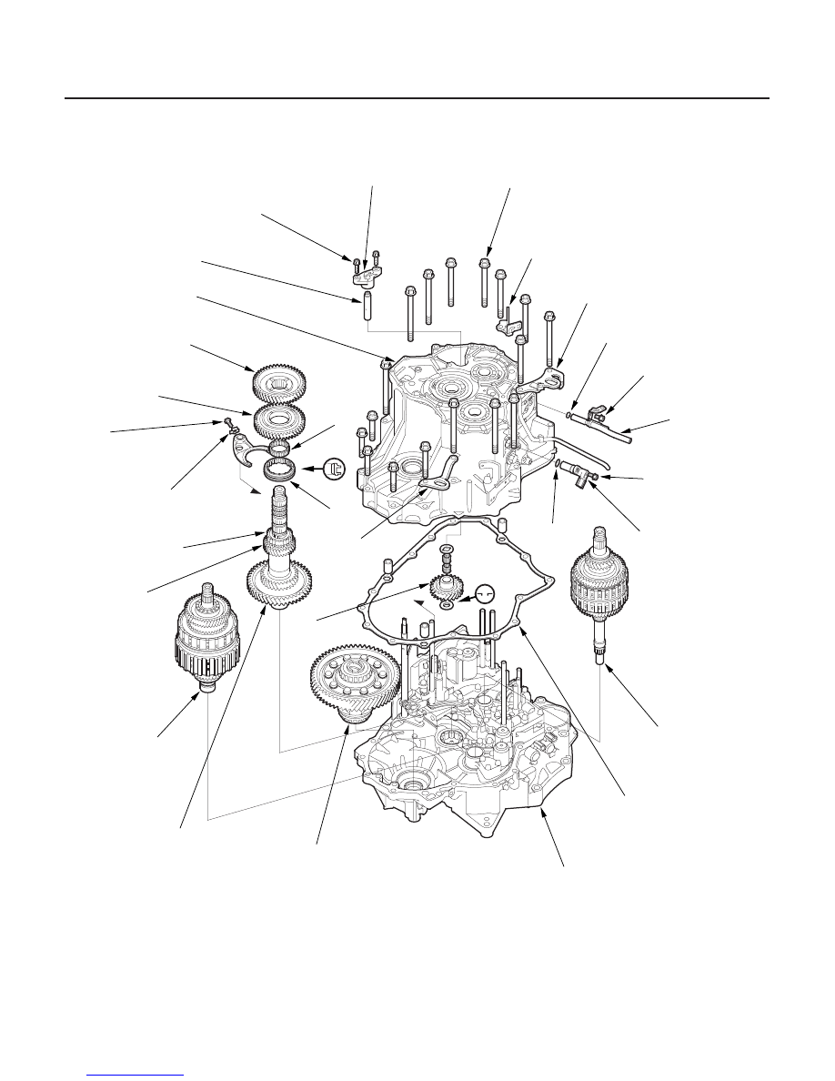
Exploded View

14-466

Transmission Housing

Shaft Assembly and Housing Installation

TRANSMISSION HOUSING
MOUNTING BOLTS
10 x 1.25 mm
44 N·m (4.5 kgf·m,
33 lbf·ft)

HARNESS CLAMP BRACKET

TRANSMISSION HANGER

TRANSMISSION HOUSING

TRANSMISSION
HANGER

REVERSE
IDLER GEAR

MAINSHAFT
SUBASSEMBLY

TORQUE CONVERTER HOUSING

DIFFERENTIAL ASSEMBLY

COUNTERSHAFT
SUBASSEMBLY

SECONDARY SHAFT
SUBASSEMBLY

COUNTERSHAFT
5TH GEAR

REVERSE SELECTOR HUB

REVERSE
SELECTOR

COUNTERSHAFT
REVERSE GEAR

COUNTERSHAFT
2ND GEAR

REVERSE IDLER GEAR
SHAFT

REVERSE IDLER GEAR
SHAFT HOLDER

LOCK WASHER

TRANSMISSION HOUSING
GASKET

ATF DIPSTICK
GUIDE PIPE

O-RING

O-RING

OUTPUT SHAFT
(COUNTERSHAFT)
SPEED SENSOR

NEEDLE
BEARING

6 x 1.0 mm
12 N·m (1.2 kgf·m,
8.7 lbf·ft)

6 x 1.0 mm
12 N·m (1.2 kgf·m,
8.7 lbf·ft)

8 x 1.25 mm
26 N·m (2.6 kgf·m,
20 lbf·ft)

6 x 1.0 mm
14 N·m (1.4 kgf·m,
10 lbf·ft)

Replace.

Replace.

Replace.

Replace.

03/07/29 09:46:16 61S0X050_140_0469

*02

*03

*04

14-467

E
6 x 1.0 mm
14 N·m (1.4 kgf·m, 10 lbf·ft)

F

B

C

D

A

A

A

NOTE: Refer to the exploded view as needed during the
following procedure.

1. Install the differential assembly in the torque

converter housing.

2. If the reverse selector hub is press-fitted type, join

the mainshaft, countershaft, and secondary shaft
together, then install them in the torque converter
housing.

3. If the reverse selector hub is not press-fitted type,

install the countershaft, mainshaft, and secondary
shaft in the torque converter housing, then install
the countershaft 5th gear and reverse selector hub
on the countershaft.

4. Turn the shift fork shaft (A) so the large chamfered

hole is facing the fork bolt hole. Then install the
shift fork (B) and reverse selector (C) together on
the shift fork shaft and countershaft (D). Secure the
shift fork to the shift fork shaft with the lock bolt (E)
and a new lock washer (F), then bend the lock
washer against the bolt head.

5. Install the needle bearing, countershaft reverse

gear, and countershaft 2nd gear on the
countershaft.

6. Place the thrust washer (A) in the transmission

housing.

7. Place the reverse idler gear (A) in the transmission

housing as shown, then slide it in the direction
shown.

(cont’d)

03/07/29 09:46:17 61S0X050_140_0470

*05

*06

14-468

Transmission Housing

Shaft Assembly and Housing Installation (cont’d)

10 x 1.25 mm
44 N·m (4.5 kgf·m, 33 lbf·ft)
17 Bolts

A

C

D

E

B

F

G

H

I

J

6 x 1.0 mm
9.8 N·m
(1.0 kgf·m,
7.2 lbf·ft)

D

D

I

8 x 1.25 mm
26 N·m (2.7 kgf·m,
20 lbf·ft)

D

B

C

A

8. Align the spring pin (A) on the control shaft (B) with

the transmission housing groove (C) by turning the
control shaft.

9. Install three dowel pins (D) and a new gasket (E) on

the torque converter housing (F).

10. Place the transmission housing (G) on the torque

converter housing, then install the transmission
housing mounting bolts along with the harness
clamp bracket (H) and transmission hangers (I).

11. Tighten the mounting bolts in two or more steps in

a crisscross pattern.

12. Install the new O-ring on the output shaft

(countershaft) speed sensor (J), then install it in the
transmission housing.

13. Engage the reverse idler gear with the countershaft

reverse gear and mainshaft reverse gear. Then
install the needle bearings (A), reverse idler gear
shaft (B), and thrust washer (C) in the reverse idler
gear, and install the reverse idler gear shaft holder
(D) on the transmission housing.

03/07/29 09:46:19 61S0X050_140_0471

*01

*02

*03

S0X4AA1E10410424251KCAT30

Special Tools Required

14-469

Transmission End Cover

End Cover, 3rd Gear, Idler Gear, and 3rd Clutch Installation

A

B

C

E

D
6 x 1.0 mm
14 N·m (1.4 kgf·m, 10 lbf·ft)

B

A

C

D

I

G

F

E

D

C

B

A

H

• Mainshaft holder

07GAB-PF50101 or 07GAB-PF50100

• Adjustable bearing puller, 25

40 mm

07736-A01000B or 07736-A01000A

1. Install the park lever (A) and park lever stop (B), on

the control shaft (C), then install the lock bolt (D)
with a new lock washer (E). Do not bend the lock
tab of the lock washer until step 28.

2. Lubricate the following parts with ATF:

• Splines of the countershaft, the park gear, and

the old locknut.

• Threads of the countershaft and the old locknut.
• Old conical spring washer.

3. Install the park gear (A) using the old locknut (B)

and a collar (C). Hold the park pawl (D) against the
park gear, then tighten the old locknut until the
shaft splines come out over the park gear splines.

NOTE:

• Do not use an impact wrench.
• Countershaft locknut has left-hand threads.

4. Remove the locknut and collar.

5. Install the thrust needle bearing (A), needle bearing

(B), 3rd gear (C), thrust needle bearing (D),
31 x 63.5 mm splined washer (E), 3rd clutch
assembly (F), and old conical spring washer (G) on
the countershaft (H). Tighten the old locknut (I) to
226 N·m (23.0 kgf·m, 166 lbf·ft).

NOTE: Use a torque wrench to tighten the locknut.
Do not use an impact wrench.

(cont’d)

03/07/29 09:46:20 61S0X050_140_0472


Content   ..  266  267  268  269   ..