Honda Odyssey 2004. Manual - part 252
*01
S0X4AA1E10410700000FCAT00
Cavity
Wire Color
Test Condition
Test: Desired Result
Possible Cause
(If result is not obtained)
14-402
A/T Gear Position Indicator
Indicator Input Test
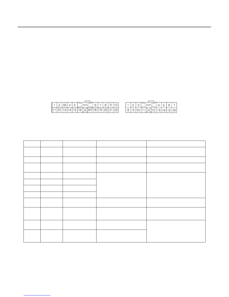
GAUGE ASSEMBLY CONNECTORS
B (22P)
C (16P)
SRS components are located in this area. Review the SRS component locations, 2002 model (see page 23-19), 2003-2004 models (see page 23-
20), and the precautions and procedures (see page 23-21) in the SRS before performing repairs or service.
1. Remove the gauge assembly from the dashboard, then disconnect the gauge assembly B (22P) and C (16P) connectors.
2. Inspect the connectors and connector terminals to be sure they are all making good contact.
• If the terminals are bent, loose, or corroded, repair them as necessary, and recheck the system.
• If the terminals look OK, make the following input tests at the gauge assembly B (22P) and C (16P) connectors.
– If a test indicates a problem, find a correct the cause, then recheck the system.
– If all the input tests prove OK, but the indicator is faulty, replace the printed circuit board.
•
•
•
•
•
•
•
•
•
•
•
•
•
•
•
B11
YEL
Ignition switch ON (II)
Check for voltage to ground:
There should be battery voltage.
Blown No. 9 (10A) fuse in the driver’s
under-dash fuse/relay box
An open in the wire
B16
BLK
Under all conditions
Check for continuity to ground:
There should be continuity.
Poor ground (G503)
An open in the wire
B22
RED/BLK
Headlights ON
Check for voltage to ground:
There should be battery voltage.
Blown No. 10 (15A) fuse in the
passenger’s under-dash fuse/relay box
An open in the wire
C4
WHT
Ignition switch ON (II)
and shift lever in R
Check for voltage to ground:
There should be 1 V or less.
There should be no battery voltage
in any other shift lever position.
Faulty transmission range switch
An open in the wire
C5
BRN
Ignition switch ON (II)
and shift lever in 1
C6
RED
Ignition switch ON (II)
and shift lever in D3
C7
BLU
Ignition switch ON (II)
and shift lever in 2
C12
GRN/BLK
Ignition switch ON (II)
and shift lever in D
Check for voltage to ground:
There should be battery voltage.
Faulty transmission range switch
Faulty PCM
An open in the wire
C13
YEL
Ignition switch ON (II)
and shift lever in D
Check for voltage to ground:
There should be 1 V or less.
There should be no battery voltage
in any other shift lever position.
Faulty transmission range switch
An open in the wire
C15
BLK/BLU
Shift lever in P
Check for continuity to ground:
There should be no continuity in any
other shift lever position.
Faulty transmission range switch
An open in the wire
C16
RED/BLK
Ignition switch ON (II)
and shift lever in N
Check for voltage to ground:
There should be 1 V or less.
There should be battery voltage in
any other shift lever position.
Wire side of female terminals
03/07/29 09:45:28 61S0X050_140_0405