Honda Odyssey 2004. Manual - part 230
*90
S0X4AA1E10400000000EAAT00
−
−
−
−
−
−
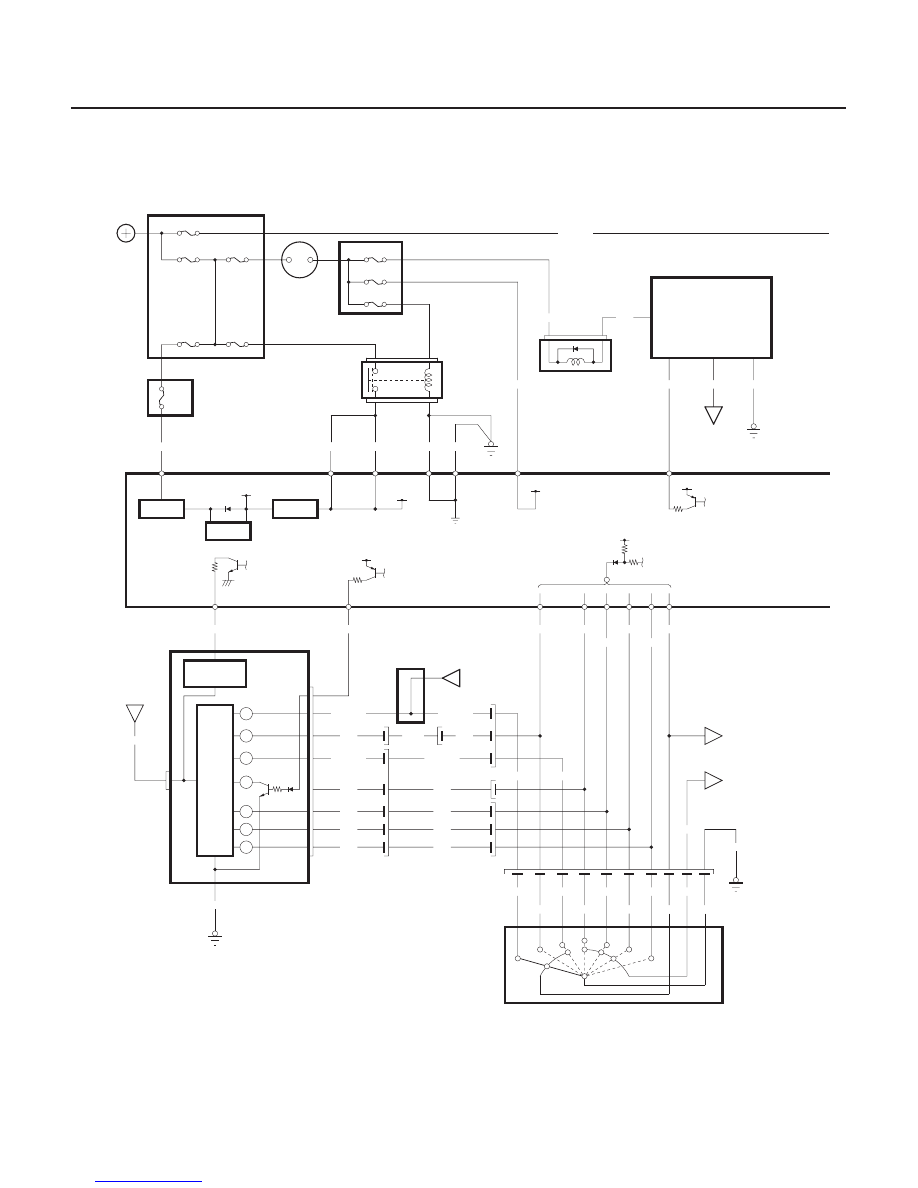
Circuit Diagram
14-314
Automatic Transmission
System Description (cont’d)
RED/BLK
BLU/BLK
D
B16
BLK
B2
WHT
WHT
YEL
YEL
BLK/YEL
D5
VB SOL
B22
GND
B11
A15
BLK
G401
B14
BLU/WHT
BLU/BLK
RED/BLK
RED
BLU
BRN
BLU/WHT
A9
ILU
A28
WHT/RED
BLK/BLU
ATP P
ILU
B12
GRN
YEL
(7.5A)
No.13
BLU/YEL
E
ST
A
PG2
B10
PG1
B2
B9
IGP2
IGP1
B1
B21
VBU
G101
BLK
BLK
YEL/BLK
To 5V
CPU
No.9 (10A)
IG1
BAT
No.54 (40A)
No.46 (15A)
BLK
G503
YEL
G101
RED/WHT
PNK
GRY
BLK/BLU
WHT
RED
YEL
GRN
BLU
BRN
YEL/BLK
BRN
BLU
RED
RED/BLK
WHT
BLK/BLU
GRN/BLK
BRN
BLU
RED
YEL
WHT
WHT/YEL
No.47 (20A)
POWERTRAIN CONTROL MODULE (PCM)
To 12V
IGNITION SWITCH
No.6 (15A)
No.1 (15A)
WHT/RED
No.41 (120A)
REGULATOR
5V
D5
D9
1
D15
D3
2
UNDER HOOD FUSE/RELAY BOX
D14
D8
D6
A14
TRANSMISSION RANGE SWITCH
1
2
N
R
P
D3
N
R
5V
REGULATOR
BATTERY
GAUGE ASSEMBLY
P
No.42 (50A)
DRIVER’S
UNDER DASH
FUSE/RELAY BOX
PASSENGER’S
UNDER DASH
FUSE/RELAY BOX
PGM FI
MAIN
RELAY
SHIFT LOCK
SOLENOID
SHIFT LOCK
SOLENOID
MULTIPLEX CONTROL
UNIT (DRIVER’S)
TRANSMISSION
RANGE SWITCH
P POSITION
ATP
R
ATP
D5
ATP
D3
ATP
2
ATP
1
ATP
NP
DRIVER’S
UNDER DASH
FUSE/RELAY
BOX
MULTIPLEX
CONTROL
UNIT
(DRIVER’S)
STARTER
CUT RELAY
CRUISE
CONTROL
UNIT
VSS
OUT
D5
IND
SPEEDOMETER
CIRCUIT
DRIVER’S
UNDER DASH
FUSE/RELAY
BOX
No.9 (10A)
DIMMING
CIRCUIT
C13
2
1
P
3
2
1
4
5
6
7
8
9
10
P
C5
B11
C7
C6
C16
C4
C15
C12
03/07/29 09:38:53 61S0X050_140_0317