Honda Odyssey 2004. Manual - part 210


  Index      Honda     Honda Odyssey 2004 - service repair manual 2004 year


Search            


Content   ..  208  209  210  211   ..


Honda Odyssey 2004. Manual - part 210


*10

*11

*12

*13

14-234

Transmission End Cover

End Cover and Idler Gear Installation (cont’d)

A

B

B

A

A

B

C

D

A

B

6 x 1.0 mm
12 N·m (1.2 kgf·m,
8.7 lbf·ft)

B

C

F

E

D

A

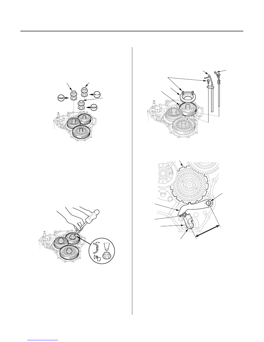
18. Lubricate the threads of each shaft, the new

locknuts, and the new conical spring washers with
ATF.

19. Install the new conical spring washers (A) in the

direction shown, and install the new locknuts (B).

20. Tighten the locknut to 167 N·m, (17.0 kgf·m, 123

lbf·ft).

NOTE:

• Use a torque wrench to tighten the locknut. Do

not use an impact wrench.

• Countershaft and secondary shaft locknuts have

left-hand threads.

21. Stake each locknut into its shaft using a 3.5 mm

punch.

22. Install the pitot flange (A) on the mainshaft idler

gear (B), then install the lubrication pitot pipe (C)
and the pitot pipe (D) on the transmission housing.

23. Set the park lever in P position, then verify that the

park pawl (A) engages the park gear (B).

24. If the park pawl does not engage fully, check the

distance between the pawl shaft (C) and the park
lever roller pin (D) (see page 14-190).

25. Tighten the lock bolt (E), and bend the lock tab of

the lock washer (F) against the lock bolt head.

03/07/29 09:35:49 61S0X050_140_0237

*14

*15

*16

14-235

B

A

A

26. Install the end cover (A) with the two dowel pins,

new O-rings, new gasket, and harness clamp
bracket (B). Tighten the 16 bolts to 12 N·m, (1.2
kgf·m, 8.7 lbf·ft).

27. Set the transmission range switch to N position.

NOTE: The transmission range switch clicks in N
position.

28. Set the control shaft (A) to the N position by turning

it.

NOTE: Be careful not to squeeze the end of the
control shaft tips together when turning into
position. If the tips are squeezed together it will
cause a faulty shift signal or position due to the
play between the control shaft and position switch.

(cont’d)

03/07/29 09:35:49 61S0X050_140_0238

*17

14-236

Transmission End Cover

End Cover and Idler Gear Installation (cont’d)

A

B

C

D

E

F

G

6 x 1.0 mm
12 N·m(1.2 kgf·m,
8.7 lbf·ft)

29. Install the transmission range switch (A) gently on

the control shaft (B), then secure it with the bolts.
Take care not to move the transmission range
switch when tightening the bolts.

30. Install the transmission range switch cover (C);

install the harness clamp (D) on the clamp bracket
(E); install the harness clamp (F) on the end cover
(G).

31. Install the ATF cooler lines and new sealing

washers. Tighten the line fittings to 28 N·m (2.9
kgf·m, 21 lbf·ft).

32. Install the breather tube.

33. Install the ATF dipstick.

03/07/29 09:35:50 61S0X050_140_0239

01

S0X4AA0E10411600000DAAT00

01

S0X4AA0E10411600000MAAT00

Standard:

0.175

0.275 mm (0.007

0.011 in.)

14-237

14-237

A/T Differential

Component Location Index

Backlash Inspection

THRUST SHIM, 76 mm

THRUST WASHER

BEARING OUTER RACE

CARRIER BEARING

FINAL DRIVEN GEAR

DIFFERENTIAL CARRIER

CARRIER BEARING

BEARING OUTER RACE

THRUST WASHER

A

B

C

A

1. Install both axles, and place the differential

assembly on V-blocks (A).

2. Check the backlash of the pinion gears (B) with a

dial indicator (C).

3. If the backlash is out of standard, replace the

differential carrier.

Replacement, page 14-240

Replacement, page 14-238

Replacement, page 14-238

Backlash Inspection,

page 14-237

Replacement, page 14-238

Replacement, page 14-240

03/07/29 09:35:52 61S0X050_140_0240


Content   ..  208  209  210  211   ..