Honda Odyssey 2004. Manual - part 179
−
−
−
−
05
06
YES
NO
YES
NO
14-110
Automatic Transmission
DTC Troubleshooting (cont’d)
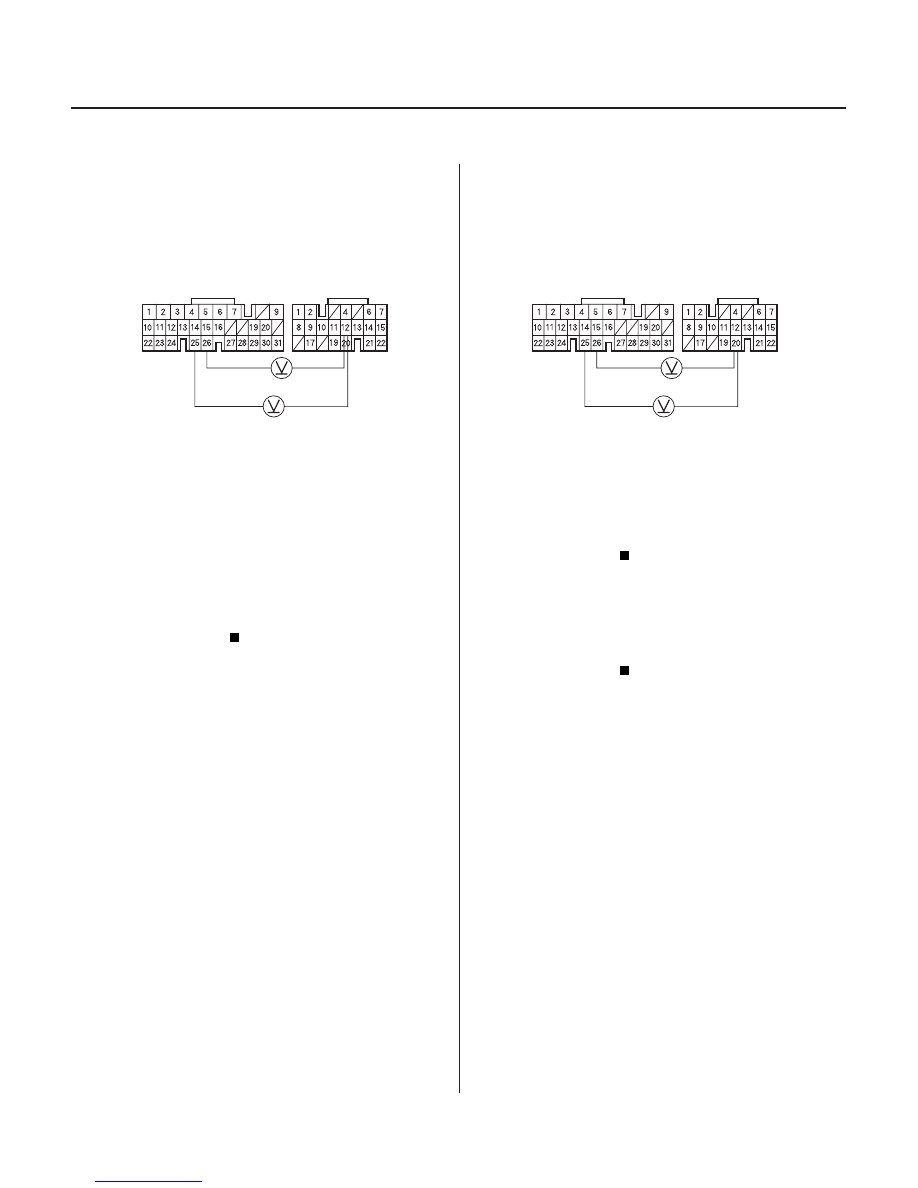
LG1 (BRN/BLK)
LG2 (BRN/BLK)
A (31P)
C (22P)
PCM CONNECTORS
ATP 2 (BLU)
LG1 (BRN/BLK)
LG2 (BRN/BLK)
A (31P)
C (22P)
PCM CONNECTORS
ATP 1 (BRN)
14. Shift to any position other than 2.
15. Measure the voltage between PCM connector
terminals C12 and A25 or A26.
Go to step 16.
Check for a short in the wire between PCM
connector terminal C12 and the transmission range
switch or A/T gear position indicator. If the wire is
OK, check for loose terminal fit in the PCM
connectors. If necessary, substitute a known-good
PCM and recheck.
16. Shift to any position other than 1.
17. Measure the voltage between PCM connector
terminals C20 and A25 or A26.
Check for loose terminal fit in the PCM
connectors. If necessary, substitute a known-good
PCM and recheck.
Check for a short in the wire between PCM
connector terminal C20 and the transmission range
switch or A/T gear position indicator. If the wire is
OK, check for loose terminal fit in the PCM
connectors. If necessary, substitute a known-good
PCM and recheck.
Wire side of female terminals
Wire side of female terminals
Is ther e batter y voltage?
Is ther e batter y voltage?
03/07/29 09:32:25 61S0X050_140_0113