Honda Odyssey 2004. Manual - part 138
−
−
−
−
−
−
05
06
07
*05
YES
NO
YES
NO
YES
NO
11-250
EGR System
DTC Troubleshooting (cont’d)
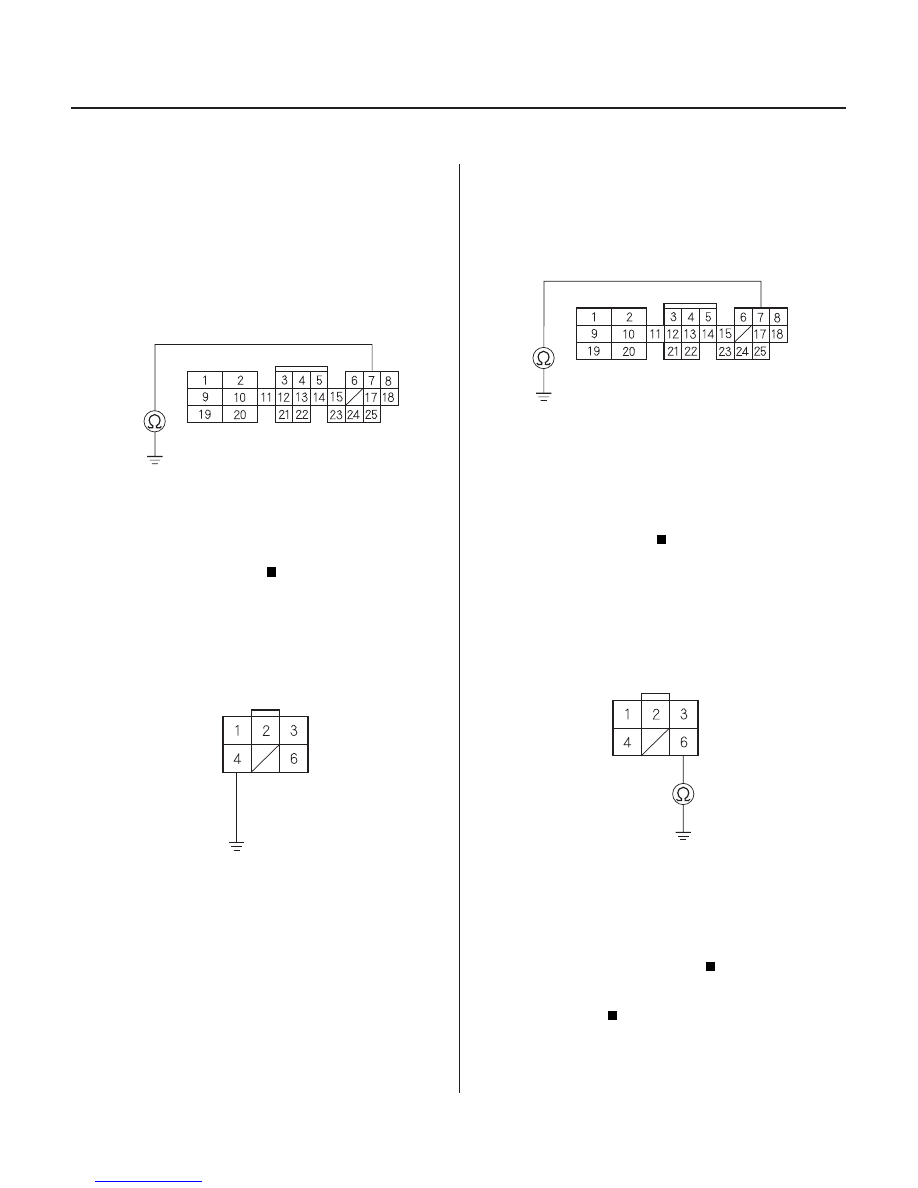
EGR (PNK)
EGR (BLU/RED)*
PCM CONNECTOR B (25P)
EGR VALVE 6P CONNECTOR
JUMPER WIRE
EGR (PNK)
EGR
(BLU/RED)*
PCM CONNECTOR B (25P)
EGR (PNK)
EGR (BLU/RED)*
EGR VALVE 6P CONNECTOR
GND (BLK)
25. Turn the ignition switch OFF.
26. Disconnect PCM connector B (25P).
27. Check for continuity between PCM connector
terminal B7 and body ground.
Repair short in the wire between the EGR
valve and the PCM (B7).
Go to step 28.
28. Connect EGR valve 6P connector terminal No. 4 to
body ground with a jumper wire.
29. Check for continuity between PCM connector
terminal B7 and body ground.
Go to step 30.
Repair open in the wire between the EGR
valve and the PCM (B7).
30. Disconnect the jumper wire from the EGR valve 6P
connector.
31. Check for continuity between EGR valve 6P
connector terminal No. 6 and body ground.
Substitute a known-good PCM and recheck
(see page 11-5). If the symptom/indication goes
away, replace the original PCM.
Repair open in the wire between the EGR
valve and G101.
Wire side of female terminals
Wire side of female terminals
Wire side of female terminals
Wire side of female terminals
Is ther e continuity?
Is ther e continuity?
Is ther e continuity?
03/07/29 09:24:49 61S0X050_110_0250