Honda Odyssey 2004. Manual - part 113


  Index      Honda     Honda Odyssey 2004 - service repair manual 2004 year


Search            


Content   ..  111  112  113  114   ..


Honda Odyssey 2004. Manual - part 113


*01

*02

S0X4AZBK77100090340FAAT10

DTC P0340

‘03-04 Models:

DTC P0341

‘03-04 Models:

DTC P0365

‘03-04 Models:

DTC P0366

‘03-04 Models:

YES

NO

YES

NO

YES

NO

11-150

PGM-FI System

DTC Troubleshooting (cont’d)

CMP SENSOR A/B 4P CONNECTOR

CMPA

CMPB

CMPA

CMPB

CMP SENSOR A/B 4P CONNECTOR

CMPA

CMPA

CMPB

CMPB

CMP Sensor A

No Signal

CMP Sensor A

Intermittent Interruption

CMP Sensor B

No Signal

CMP Sensor B

Intermittent Interruption

1. Reset the PCM (see page 11-4).

2. Start the engine.

Go to step 3.

Intermittent failure, system is OK at this time.

Check for poor connections or loose terminals at
the CMP sensor A/B and at the PCM.

3. Turn the ignition switch OFF.

4. Disconnect the CMP sensor A/B 4P connector.

5. Measure resistance between the terminals of the

indicated sensor (see table).

CMP A

P0340

1

C20

GRN

P0341

2

C21

RED

CMP B

P0365

3

C29

YEL

P0366

4

C30

BLK

Go to step 6.

Replace the CMP sensor A/B

(see page 6-60).

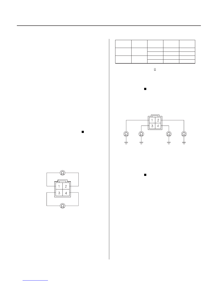
6. Check for continuity to body ground on both

terminals of the indicated sensor individually.

Replace the CMP sensor A/B

(see page 6-60).

Go to step 7.

7. Reconnect the CMP sensor A/B 4P connector.

8. Disconnect PCM connector C (31P).

SENSOR

SENSOR

TERMINAL

PCM

TERMINAL

WIRE

COLOR

DTC

Terminal side of male terminals

Terminal side of male terminals

Is DT C P0340, P0341, P0365, or P0366
indicated?

Is ther e 1,850

2,450

?

Is ther e continuity?

03/07/29 09:21:34 61S0X050_110_0150

*03

*04

S0X4AZ1K77100090560FAAT00

YES

NO

YES

NO

YES

NO

YES

NO

DTC P0560

’01 Model:

11-151

11-151

PCM CONNECTOR C (31P)

CMPA
(GRN)

CMPA
(RED)

CMPB
(YEL)

CMPB
(BLK)

PCM CONNECTOR C (31P)

CMPA

(GRN)

CMPB
(YEL)

9. Measure resistance between the terminals of the

indicated sensor on the PCM connector (see table).

SENSOR

DTC

PCM

TERMINAL

WIRE

COLOR

CMP A

P0340

C20

GRN

P0341

C21

RED

CMP B

P0365

C29

YEL

P0366

C30

BLK

Go to step 10.

Repair open in the indicated sensor wires (see

table).

10. Check for continuity between body ground and

PCM connector terminals C20 and/or C29
individually.

Repair short in the indicated sensor wires.

Substitute a known-good PCM and recheck

(see page 11-5). If the symptom/indication goes
away, replace the original PCM.

NOTE: If the No. 13 CLOCK BACK UP (7.5A) fuse in the
passenger’s under-dash fuse/relay box is removed and
the engine is started, MIL will come on and the PCM will
store DTC P0560.

1. Reset the PCM (see page 11-4).

2. Start the engine.

Go to step 3.

Intermittent failure, system is OK at this time.

Check for poor connections or loose terminal at the
No. 13 CLOCK BACK UP (7.5A) fuse in the
passenger’s under-dash fuse/relay box and PCM.

3. Turn the ignition switch OFF.

4. Inspect the No. 13 CLOCK BACK UP (7.5A) fuse in

the passenger’s under-dash fuse/relay box.

Go to step 5.

Check for these problems:

• Repair short in the wire between the PCM (A1)

and No. 13 CLOCK BACK UP (7.5A) fuse in the
passenger’s under-dash fuse/relay box.

• Repair short in the wire the back up circuit (see

page 22-80).

(cont’d)

Low Voltage in PCM

Back Up Circuit

Wire side of female terminals

Wire side of female terminals

Is ther e 1,850

2,450

?

Is ther e continuity?

Is DT C P0560 indicated?

Is the f use OK ?

03/07/29 09:22:45 61S0X050_110_0151

01

S0X4A00K77100091106FAAT00

YES

NO

YES

NO

DTC P1106:

11-152

11-152

PGM-FI System

DTC Troubleshooting (cont’d)

PCM CONNECTOR A (31P)

VBU
(WHT/YEL)

5. Measure voltage between PCM connector terminal

A1 and body ground.

Substitute a known-good PCM and recheck

(see page 11-5). If the symptom/indication goes
away, replace the original PCM.

Repair open in the wire between the PCM (A1)

and the No. 13 CLOCK BACK UP (7.5A) fuse in the
passenger’s under-dash fuse/relay box.

1. Reset the PCM (see page 11-4).

2. Start the engine. Hold the engine at 3,000 rpm with

no load (in Park or neutral) until the radiator fan
comes on, then let it idle.

3. Test-drive with the transmission in 2 position.

4. Accelerate for 5 seconds using wide open throttle.

5. Check for a Temporary DTC with the scan tool or

the HDS.

Substitute a known-good PCM and recheck

(see page 11-5). If the symptom/indication goes
away, replace the original PCM.

Intermittent failure, system is OK at this

time.

BARO Sensor Circuit Range/

Performance Problem

Wire side of female terminals

Is ther e batter y voltage?

Is T empor ar y DT C P1106 indicated?

03/07/29 09:22:45 61S0X050_110_0152

S0X4A00K77100091107FAAT00

01

S0X4AZ6K77100091297FAAT00

DTC P1107:

DTC P1108:

DTC P1297

’99-00, ’02-04 Models:

YES

NO

YES

NO

YES

NO

11-153

11-153

ELD 3P CONNECTOR

ELD (GRN/RED)

BARO Sensor Circuit Low Voltage

BARO Sensor Circuit High

Voltage

ELD

Circuit Low Voltage

1. Reset the PCM (see page 11-4).

2. Turn the ignition switch ON (II).

Substitute a known-good PCM and recheck

(see page 11-5). If the symptom/indication goes
away, replace the original PCM.

Intermittent failure, system is OK at this

time.

1. Reset the PCM (see page 11-4).

2. Start the engine.

3. Turn on the headlights.

Go to step 4.

Intermittent failure, system is OK at this time.

Check for poor connections or loose terminals at
the ELD and the PCM.

4. Turn the ignition switch and the headlights OFF.

5. Disconnect the ELD 3P connector.

6. Turn the ignition switch ON (II).

7. Measure voltage between body ground and ELD 3P

connector terminal No. 3.

Replace the ELD.

Go to step 8.

(cont’d)

Wire side of female terminals

Is DT C P1107 or P1108 indicated?

Is DT C P1297 indicated?

Is ther e about 5 V ?

03/07/29 09:22:45 61S0X050_110_0153


Content   ..  111  112  113  114   ..