Honda Odyssey 2004. Manual - part 70


  Index      Honda     Honda Odyssey 2004 - service repair manual 2004 year


Search            


Content   ..  68  69  70  71   ..


Honda Odyssey 2004. Manual - part 70


*01

10-4

Cooling System

Component Location Index (cont’d)
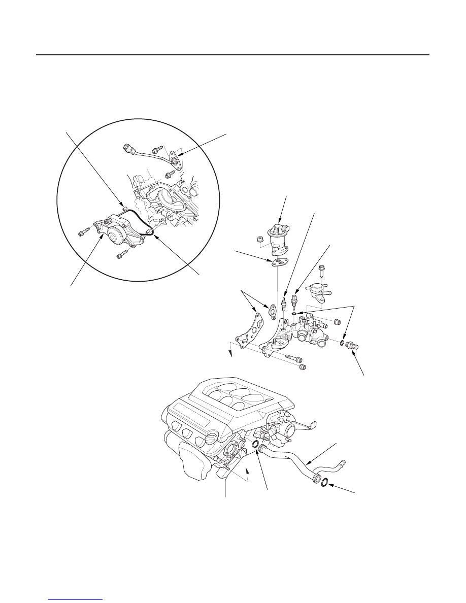
WATER PUMP

O-RING

RADIATOR FAN SWITCH B

DOWEL PIN

EXHAUST GAS RECIRCULATION
(EGR) VALVE

ENGINE COOLANT
TEMPERATURE (ECT)
SENSOR

O-RINGS

GASKET

COOLANT TEMPERATURE
GAUGE SENDING UNIT
(1999-2000 models)

GASKETS

RADIATOR FAN SWITCH A

O-RING

CONNECTING PIPE

O-RING

Inspection, page 10-12
Replacement, page 10-12

Test, page 10-9

03/07/29 09:15:11 61S0X050_100_0004

*01

S0X4AZ0A14400017351FEAT00

*01

S0X4AZCA14400017351FAAT00

1999-2000 models

Coolant Temperature Gauge Needle Does
Not Move at All - 2001 model

YES

NO

10-5

10-5

Coolant Temperature Gauge Test

A

B

PCM CONNECTOR E (31P)

ECTOUT
(YEL/GRN)

1. Check the No. 9 (7.5A) fuse in the under-dash fuse/

relay box before testing.

2. Make sure the ignition switch is OFF, then

disconnect the YEL/GRN wire (A) from the coolant
temperature gauge sending unit (B), and ground it
with a jumper wire.

3. Turn the ignition switch ON (II). Check that the

pointer of the coolant temperature gauge starts
moving toward the ‘‘H’’ mark. Turn the ignition
switch OFF before the pointer reaches ‘‘H’’ on the
gauge dial. Failure to do so may damage the gauge.

• If the pointer of the gauge does not move at all,

check for an open in the YEL/GRN wire. If the
wires are OK, replace the coolant temperature
gauge.

• If the coolant temperature gauge works, test the

coolant temperature gauge sending unit.

1. Turn the ignition switch OFF, and connect

powertrain control module (PCM) connector
terminal E14 to body ground with a jumper wire.

2. Turn the ignition switch ON (ll).

Substitute a known-good PCM and recheck

(see page 11-5). If the symptom/indication goes
away, replace the original PCM (see page 11-4).

Go to step 3.

3. Turn the ignition switch OFF, and disconnect the

negative cable from the battery. Then disconnect
PCM connector E (31P).

(cont’d)

Wire side of female terminals

Af ter 30 seconds or mor e, does the temper atur e
gauge needle move to the hot side?

03/07/29 09:15:12 61S0X050_100_0005

*02

*03

*04

YES

NO

YES

NO

YES

NO

Coolant Temperature Gauge Needle Does
Not Move at All - 2002-2004 models

10-6

Cooling System

Coolant Temperature Gauge Test (cont’d)

PCM CONNECTOR E (31P)

ECTOUT
(YEL/GRN)

PCM CONNECTOR E (31P)

ECTOUT
(YEL/GRN)

(YEL/GRN)

GAUGE ASSEMBLY CONNECTOR C (16P)

PCM CONNECTOR A (32P)

ECTOUT
(YEL/GRN)

4. Connect the negative cable to the battery. Turn the

ignition switch ON (II), and measure voltage
between PCM connector terminal E14 and body
ground.

Replace the fuel and temperature gauge

assembly.

Go to step 5.

5. Turn the ignition switch OFF, and check for

continuity between PCM connector terminal E14
and gauge assembly connector terminal C2.

Replace the fuel and temperature gauge

assembly.

Repair an open in the wire between PCM

connector terminal E14 and gauge connector
terminal C2.

1. Turn the ignition switch OFF, and connect

powertrain Control Module (PCM) connector
terminal A31 to body ground with a jumper wire.

2. Turn the ignition switch ON (ll).

Substitute a known-good PCM and recheck

(see page 11-5). If the symptom/indication goes
away, replace the original PCM (see page 11-4).

Go to step 3.

3. Turn the ignition switch OFF, and disconnect the

negative cable from the battery. Then disconnect
PCM connector A (32P).

Wire side of female terminals

Wire side of female terminals

Wire side of female terminals

Is ther e about 5 V ?

Is ther e continuity?

Af ter 30 seconds or mor e, does the temper atur e
gauge needle move to the hot side?

03/07/29 09:15:12 61S0X050_100_0006

*05

*06

YES

NO

YES

NO

YES

NO

YES

NO

Coolant Temperature Gauge Needle Goes
Past the Hot Mark - 2001 model

10-7

PCM CONNECTOR A (32P)

ECTOUT
(YEL/GRN)

PCM CONNECTOR A (32P)

ECTOUT
(YEL/GRN)

(YEL/GRN)

GAUGE ASSEMBLY CONNECTOR C (16P)

4. Connect the negative cable to the battery. Turn the

ignition switch ON (ll), and measure voltage
between PCM connector terminal A31 and body
ground.

Replace the fuel and temperature gauge

assembly.

Go to step 5.

5. Turn the ignition switch OFF, and check for

continuity between PCM connector terminal A31
and gauge assembly connector terminal C2.

Replace the fuel and temperature gauge

assembly.

Repair an open in the wire between PCM

connector terminal A31 and gauge connector
terminal C2.

1. Turn the ignition switch OFF, and disconnect the

negative cable from the battery. Then disconnect
PCM connector E (31P).

2. Connect the negative cable to the battery. Turn the

ignition switch ON (II) and watch the coolant
temperature gauge.

Go to step 3.

Substitute a known-good PCM and recheck,

(see page 11-5). If the symptom/indication goes
away, replace the original PCM (see page 11-4).

3. Turn the ignition switch OFF, then turn it ON (II)

again, and watch the coolant temperature gauge.

Replace the fuel and temperature gauge

assembly.

The temperature gauge needle went past the

Hot mark after about 30 seconds or more. Go to
step 4.

4. Turn the ignition switch OFF, and disconnect the

gauge assembly connector C (16P).

(cont’d)

Wire side of female terminals

Wire side of female terminals

Is ther e about 5 V ?

Is ther e continuity?

Does the temper atur e gauge needle move at all?
( you may have to watch it f or about 30 seconds.)

Does the temper atur e gauge needle immediately
go past the Hot mar k?

03/07/29 09:15:13 61S0X050_100_0007


Content   ..  68  69  70  71   ..