Honda Odyssey 2004. Manual - part 60


  Index      Honda     Honda Odyssey 2004 - service repair manual 2004 year


Search            


Content   ..  58  59  60  61   ..


Honda Odyssey 2004. Manual - part 60


01

02

*01

S0X4A00A18360200000KBAT00

Disassembly

7-18

Engine Block

Piston, Pin, and Connecting Rod Replacement

A

B

A

1. Remove the piston from the cylinder block (see

page 7-12).

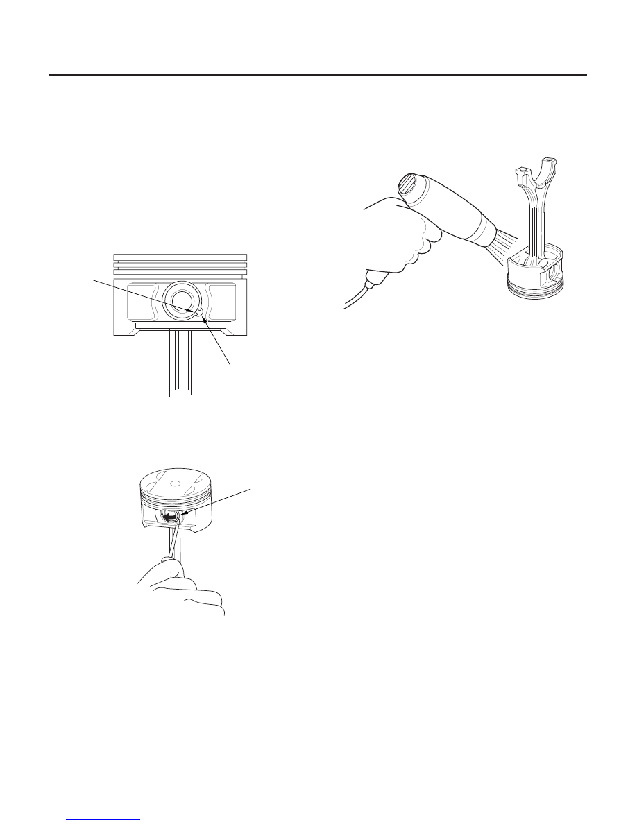
2. Apply new engine oil to the piston pin snap rings

(A) and turn them in the ring grooves until the end
gaps are lined up with the cutouts in the piston pin
bores (B).

NOTE: Take care not to damage the ring grooves.

3. Remove both snap rings (A). Start at the cutout in

the piston pin bore. Remove the snap rings
carefully so they do not go flying or get lost. Wear
eye protection.

4. Heat the piston and connecting rod assembly to

approximately 158°F (70°C), then remove the
piston pin.

03/07/29 09:13:04 61S0X050_070_0018

*02

*03

*04

*05

Inspection

Piston Pin Diameter
Standard (New): 21.962

21.965 mm

(0.8646

0.8648 in.)

Service Limit:

21.954 mm (0.8643 in.)

Piston Pin-to-Piston Clearance
Standard (New):

0.0050 to

0.0010 mm

(

0.00020 to

0.00004 in.)

Service Limit:

0.004 mm (0.0002 in.)

Piston Pin-to-Connecting Rod Clearance
Standard (New): 0.005

0.014 mm

(0.0002

0.0006 in.)

Service Limit:

0.019 mm (0.0007 in.)

7-19

NOTE: Inspect the piston, piston pin and connecting rod
when they are at room temperature.

1. Measure the diameter of the piston pin.

2. Zero the dial indicator to the piston pin diameter.

3. Check the difference between the piston pin

diameter and piston pin hole diameter on the
piston.

4. Measure the piston pin-to-connecting rod clearance.

(cont’d)

03/07/29 09:13:05 61S0X050_070_0019

08

*06

10

Reassembly

7-20

Engine Block

Piston, Pin, and Connecting Rod Replacement (cont’d)

A

D

D

A

B

C

1. Install a piston pin snap ring (A).

2. Coat the piston pin bore in the piston, the bore in

the connecting rod, and the piston pin with new
engine oil.

3. Heat the piston to about 158°F (70°C).

4. Install the piston pin (A). Assemble the piston (B)

and connecting rod (C) with the embossed marks
(D) on the same side.

5. Install the remaining snap ring.

03/07/29 09:13:05 61S0X050_070_0020

02

*01

S0X4A00A18360245611KBAT00

Piston Ring End-Gap

Top Ring
Standard (New): 0.20

0.35 mm

(0.008

0.014 in.)

Service Limit:

0.60 mm (0.024 in.)

Second Ring
Standard (New): 0.40

0.55 mm

(0.016

0.022 in.)

Service Limit:

0.70 mm (0.028 in.)

Oil Ring
Standard (New): 0.20

0.70 mm

(0.008

0.028 in.)

Service Limit:

0.80 mm (0.031 in.)

7-21

Piston Ring Replacement

B

A

15

20 mm

(0.6

0.8 in)

B

A

1. Remove the piston from the cylinder block (see

page 7-12).

2. Using a ring expander (A), remove the old piston

rings (B).

3. Clean all the ring grooves throughly with a

squared-off broken ring or ring groove cleaner with
a blade to fit the piston grooves. File down the
blade if necessary. Top ring and second ring
grooves are 1.2 mm (0.05 in.) wide, and the oil ring
groove is 2.8 mm (0.11 in.) wide. Do not use a wire
brush to clean the ring grooves, or cut the ring
grooves deeper with the cleaning tool.

NOTE: If the piston is to be separated from the
connecting rod, do not install new rings yet.

4. Using a piston, push a new ring (A) into the

cylinder bore 15

20 mm (0.6

0.8 in.) from the

bottom.

5. Measure the piston ring end-gap (B) with a feeler

gauge:

• If the gap is too small, check to see if you have

the proper rings for your engine.

• If the gap is too large, recheck the cylinder bore

diameter against the wear limits (see step 4 on
page 7-16).

• If the bore is over the service limit, the cylinder

block must be rebored.

(cont’d)

03/07/29 09:13:06 61S0X050_070_0021


Content   ..  58  59  60  61   ..