Honda Civic. Manual - part 95


  Index      Honda     Honda Civic - service repair manual 2006-2009 year


Search            


Content   ..  93  94  95  96   ..


Honda Civic. Manual - part 95


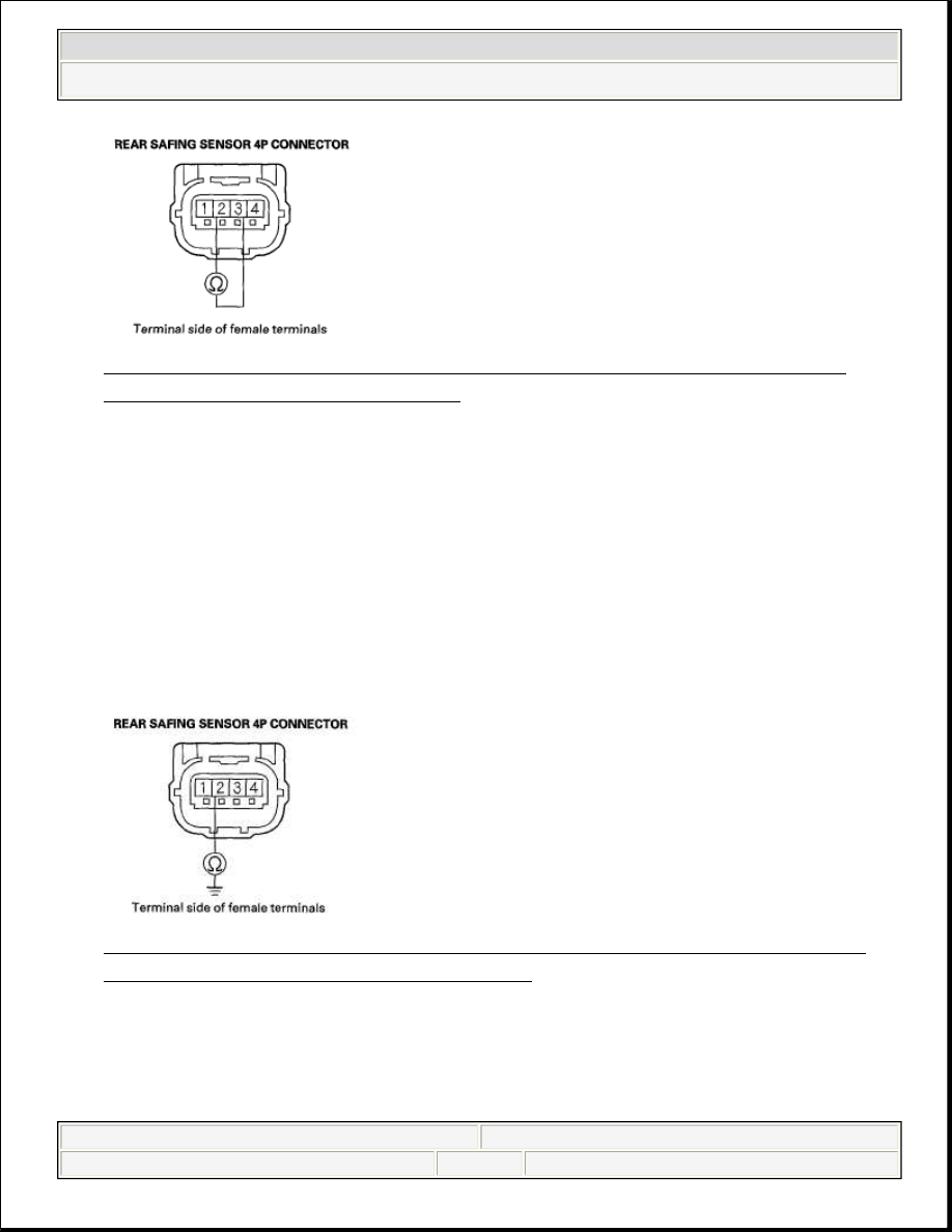
Fig. 280: Measuring Resistance Between No. 2 And No. 3 Terminal Of 
Rear Safing Sensor 4P Connector
 
Courtesy of AMERICAN HONDA MOTOR CO., INC. 

Is the resistance as specified?  

YES -Go to step 11. 

NO -Short in the floor wire harness; replace the floor wire harness. 

11. Measure the resistance between the No. 2 terminal of the rear safing sensor 4P 

connector and body ground. There should be an open circuit or at least 1 M 
ohms. 

Fig. 281: Measuring Resistance Between No. 2 Terminal Of Rear Safing 
Sensor 4P Connector And Body Ground
 
Courtesy of AMERICAN HONDA MOTOR CO., INC. 

Is the resistance as specified?  

YES -Go to step 12. 


2008 Honda Civic EX 

2006-08 RESTRAINTS SRS (Supplemental Restraint System) - Civic (Except Hybrid)


NO -Short to ground in the floor wire harness; replace the floor wire harness. 

12. Measure the resistance between the No. 3 terminal of the rear safing sensor 4P 

connector and body ground. There should be an open circuit or at least 1 M 
ohms. 

Fig. 282: Measuring Resistance Between No. 3 Terminal Of Rear Safing 
Sensor 4P Connector And Body Ground
 
Courtesy of AMERICAN HONDA MOTOR CO., INC. 

Is the resistance as specified?  

YES -Go to step 13. 

NO -Short to ground in the floor wire harness; replace the floor wire harness. 

13. Turn the ignition switch ON (II).  
14. Measure the voltage between the No. 2 terminal of the rear safing sensor 4P 

connector and body ground. There should be 1 V or less. 

Fig. 283: Measuring Voltage Between No. 2 Terminal Of Rear Safing 


2008 Honda Civic EX 

2006-08 RESTRAINTS SRS (Supplemental Restraint System) - Civic (Except Hybrid)


Sensor 4P Connector And Body Ground 
Courtesy of AMERICAN HONDA MOTOR CO., INC. 

Is the voltage as specified?  

YES -Go to step 15. 

NO -Short to power in the floor wire harness; replace the floor wire harness. 

15. Measure the voltage between the No. 3 terminal of the rear safing sensor 4P 

connector and body ground. There should be 1 V or less. 

Fig. 284: Measuring Voltage Between No. 3 Terminal Of Rear Safing 
Sensor 4P Connector And Body Ground
 
Courtesy of AMERICAN HONDA MOTOR CO., INC. 

Is the voltage as specified?  

YES -Go to step 16. 

NO -Short to power in the floor wire harness; replace the floor wire harness. 

16. Turn the ignition switch OFF.  
17. Connect the SRS inflator simulator (jumper connector) and the red lead (A) of 

simulator lead L to the floor wire harness 4P connector (B) at the left side 
impact sensor (first). 


2008 Honda Civic EX 

2006-08 RESTRAINTS SRS (Supplemental Restraint System) - Civic (Except Hybrid)


Fig. 285: Identifying Floor Wire Harness 4P Connector 
Courtesy of AMERICAN HONDA MOTOR CO., INC. 

18. Measure the resistance between the No. 2 and No. 3 terminals of the rear safing 

sensor 4P connector. There should be 0-1 ohms. 

Fig. 286: Measuring Resistance Between No. 2 And No. 3 Terminals Of 
Rear Safing Sensor 4P Connector
 
Courtesy of AMERICAN HONDA MOTOR CO., INC. 

Is the resistance as specified?  

YES -Faulty rear safing sensor or poor connection at the floor wire harness 4P 
connector and the rear safing sensor. Check the connection between the 
connector and the rear safing sensor. If the connection is OK, replace the rear 
safing sensor (see REAR SAFING SENSOR REPLACEMENT). 

NO -Open in the floor wire harness; replace the floor wire harness. 


2008 Honda Civic EX 

2006-08 RESTRAINTS SRS (Supplemental Restraint System) - Civic (Except Hybrid)


Content   ..  93  94  95  96   ..