Great Wall Florid. Manual - part 29


  Index      Great Wall     Great Wall Florid - service repair manual 2008 year


Search            copyright infringement  


Content   ..  27  28  29  30   ..


Great Wall Florid. Manual - part 29


GWFLORID Maintenance Manual

114

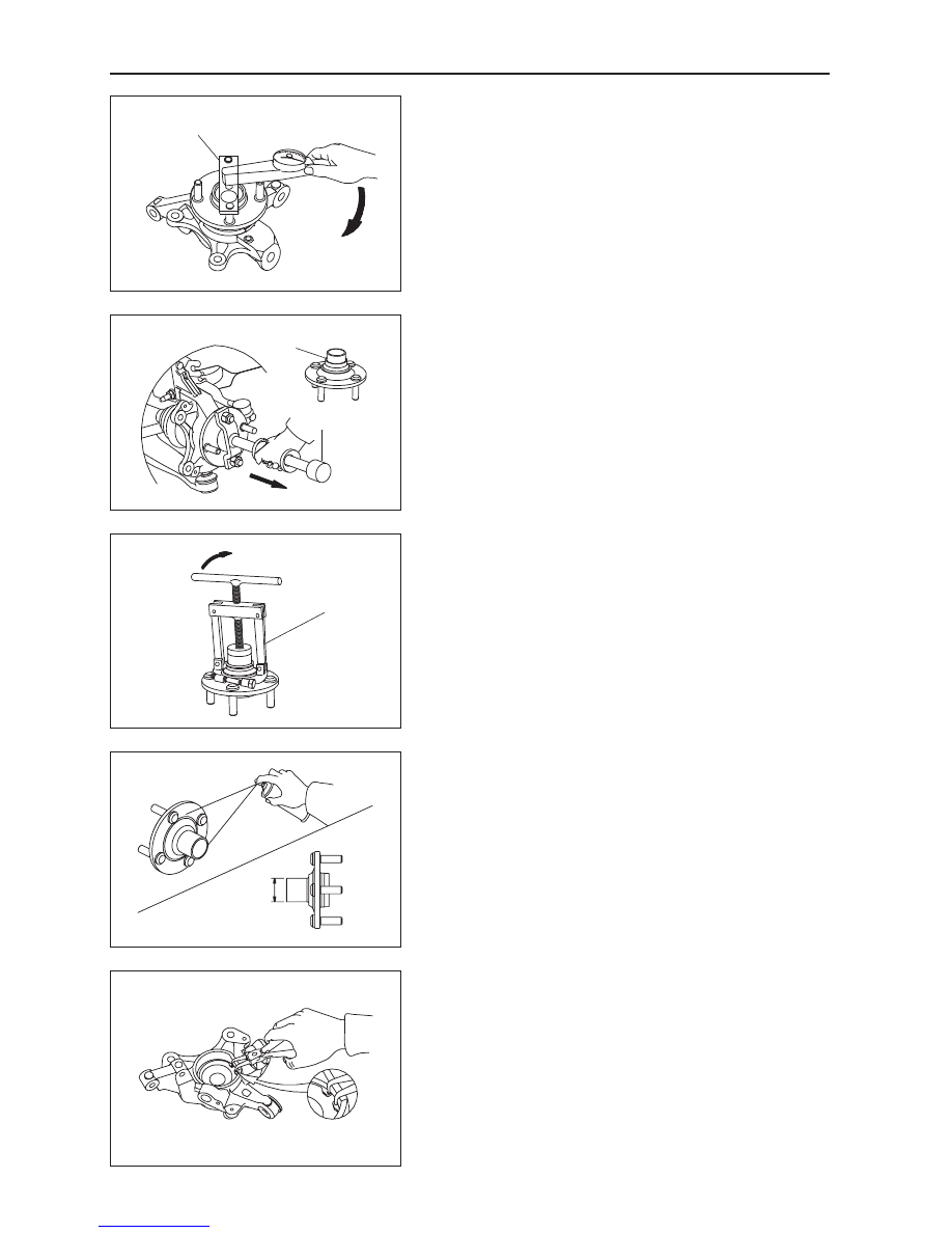
(d)  Measure the front hub bearing's starting torque.

Put the SST on the wheel bolts which are at the symmetric 

locations. Put a dial torque wrench on the SST to slowly 

rotate the flange assembly (45°/4s), requiring a starting 

torque range of 0.1-0.3 N·m.

If the bearing rotation is not flexible, the front hub flange 

plate surface movement inaccurate, or front hub bearing 

starting torque is too much. The assembly must be replaced.

Steering knuckle's front hub bearing and 
front hub flange assembly

1.  Removal and inspection of front hub flange assembly.

(a)  Use SST like a hand held travel hammer to repeatedly 

hammer off the front hub flange assembly from the 

steering knuckle and front hub bearing. Remove the 

front hub with bearing's inner ring.

(b)  Remove the bearing's inner ring on the front hub.

Use SST to remove the bearing's inner ring.

SST

    SST

Bearing inner ring

         SST

(c)  Use dye penetrant to inspect the front hub flange for 

cracks, which should be replaced if found.

(d)  If one would like to continue using the front hub flange 

assembly, first inspect the dimensions for the mounting 

area  of  the  bearing  for  inaccurate  dimensions.  If 

oversized, replace.

Measurement range: Φ38

+0.025 

+0.009


mm

2.  Remove the steering knuckle's front hub bearing.

3.  Remove the snap ring for hole 72.

Use a bent nose retaining ring caliper for holes to remove the 

snap ring for hole 72.

115

Brake System

4.  Replace the removed bearing's inner ring back to the 

bearing's original position.

5.  Press out the front hub bearing from inside of the steer-

ing knuckle.

On the press, withstand the bearing inner ring that was put 

on with SST, and press out the entire front hub bearing.

Caution: The front hub bearing assembly is a disposable 

part, which needs to be replaced with a new one.

Steering knuckle and hub brake assembly 
installation

1.  On the press, press the front hub bearing assembly 

into the steering knuckle hole bearing mounting posi-

tion with SST.

SST

SST

SST

6.  If the steering knuckle has no cracks and one would 

like to continue to use it, first inspect the bearing's 

mounting location dimensions of the steering knuckle's 

inner hole. If the measurements are oversized, replace 

the steering knuckle.

Measurement range: Φ71

-0.032 

-0.062

 mm

2.  Press the front hub flange assembly.

On the press, press the front hub flange into the front hub 

bearing mounting position using SST.

SST

SST

GWFLORID Maintenance Manual

116

3.  Examine the front hub flange plate surface runout.

Examining methods are the same as the methods used 

during disassembly. Plate surface runout should not exceed 

0.03 mm.

4.  Examine the front hub bearing assembly's starting 

torque.

Examining methods are the same as the methods used during 

disassembly. Put the SST on the wheel bolts which are at the 

symmetrical locations. Put a dial torque wrench on the SST to 

slowly rotate the flange's flange assembly (45°/4s), which re-

quires a starting torque range of 0.1-0.3 N·m

5.  Install the snap ring for hole 72.

Use a bent nose retaining ring caliper for holes to install the 

snap ring for hole 72 at the steering knuckle's retaining ring 

mounting position.

6.  Install the steering knuckle's front hub bearing and 

front hub flange assembly.  

7.  Install the front brake disc cover.

Install the front brake disc cover on the steering knuckle, and 

tighten the bolt to the set torque.

Tightening torque: 9±2 N·m

SST

8.  Install the front brake disc.

117

Brake System

9.  Examine the front brake disc plate surface runout.

When measuring, tighten the two wheel nut's symmetrical 

locations. The front brake disc's brake linings runout on the 

two sides should be less than 0.11 mm.

10. Install the brake caliper assembly.

Install the brake caliper on the steering knuckle, and tighten 

the bolt according to the set torque.

Tightening torque: 100±10 N·m


Content   ..  27  28  29  30   ..