Great Wall Florid. Manual - part 27


  Index      Great Wall     Great Wall Florid - service repair manual 2008 year


Search            copyright infringement  


Content   ..  25  26  27  28   ..


Great Wall Florid. Manual - part 27


GWFLORID Maintenance Manual

106

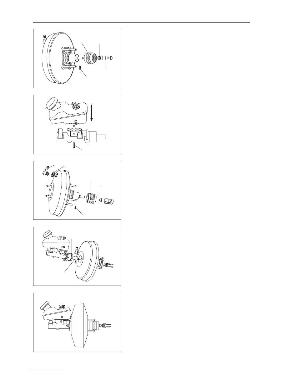
4.  Remove the dust cover.

If necessary to replace the dust cover, replace it using the 

following steps.

(a)  Twist off the rod clevis.

(b)  Screw off the nut.

(c)  Pull out the split ring.

(d)  Pull out the dust cover.

Removal  of  the  vacuum  booster  with  brake  cylinder 

assembly is now complete.

Vacuum booster with brake cylinder assem-
bly installation

1.  Install the brake cylinder assembly.

Tighten the cover of the brake reservoir, place the outlet 

port of the brake reservoir against the master cylinder inlet, 

push the brake reservoir assembly into the master cylinder 

assembly, and then insert the cylindrical pin to complete the 

installation.

Caution:  Check  and  ensure  the  cleanliness  of  the 

reservoir outlet port and master cylinder inlet. Do not 

lose the sealing ring inside the master cylinder inlet.

2.  Installation of the vacuum booster assembly.

Install each part of booster using the following steps.

(a)  Install the check valve seat.

(b)  Install the check valve.

(c)  Install the dust cover.

(d)  Install the split ring.

(e)  Install the lock nut.

(f)  Install the rod clevis.

3.  Installaion of the vacuum booster assembly and brake 

cylinder assembly.

(a)  Install the rectangular sealing ring, and then place the 

brake pump assembly into the front case’s housing. Pay 

attention when pushing the booster's push rod head into 

the first piston hole.

(b)  Put the two holes of the cylinder body’s flange surface 

into the front case bolts of the vacuum booster, and 

then tighten the nuts with a torque wrench.

Tightening torque: 20-26 N·m

4.  The  installation  of  the  vacuum  booster  with  brake 

cylinder assembly is the reversed procedure of its 

removal. Hence no more elaboration will be provided 

here.

Tightening torque of the four lock bolts on the brake 

pedal: 23±3 N·m

Tightening torque of master cylinder outlet port rigid 

pipe: 15 N·m

Rod clevis

Nut

Split ring

Dust cover

Elastic cylindrical pin

Check valve Check valve seat

Lock nut

Rod clevis

Split ring

Dust cover

Rectangular sealing ring

First piston

107

Brake System

Anti-lock Brake System

ABS/EBD introduction

1.  Operation

The vehicle's Anti-lock Brake System (ABS) is a type of increasingly popular brake safety device. It detects the 

wheel's speed using wheel speed sensor detection. After signal processing, the wheel speed will be transferred 

to the computer, which controls the solenoid valve’s operating condition and the pressure inside the brake wheel 

cylinder to avoid wheel locking by using certain calculations and control methods based on the wheel speed. 

ABS helps the vehicle to avoid sliding, deviation, fishtailing, and losing steering control capacity. ABS improves 

the vehicle’s handling capability, stability and shortens braking distance. It also helps the vehicle to avoid the 

partial wear and tear of wheels, hence improves the tire's useful life.

Electronic Brake Distribution (EBD) is used to adjust the vehicle's rear wheel brake pressure by using the ABS 

components when the ABS does not respond to vehicle braking. It is also used to balance the vehicle’s front and 

rear wheel brake pressure, maximizing the vehicle's braking efficiency. EBD uses the ABS components, yet its 

controlling logic is independent from the ABS. After the ABS responds, the EBD will disengage.

2.  Basic structure 

3.  ABS working process

(a)  Pressure rising phase: While service braking, oil pressure output from the pump passes the inlet solenoid 

valve and enters the brake wheel cylinder. The brake generates braking force and the wheel speed sharply 

declines until the ABS control unit detects that the wheel is starting to lock via the wheel speed sensor 

detection.

(b)  Pressure maintaining phase: When the ABS control unit detects that the wheel is starting to lock via wheel 

speed sensor signal, the inlet solenoid valve closes, with the outlet solenoid valve shut as usual. The 

pressure maintaining phase thus begins.

(c)  Pressure drop phrase: During the pressure maintaining phase, the wheels tend to lock further. This brings 

the ABS into the pressure drop phrase. With the inlet valve closed and the outlet valve open, the hydraulic 

pump starts working, and brake fluid returns to the brake pump from the wheel cylinder by passing through 

the low pressure accumulator. The brake pressure reduces and the brake pedal bounces back.

(d)  Pressure maintaining phase: With the degree of wheel locking decreases and wheel speed begins to 

increase, the pressure maintaining phrase begins.

(e)  Next cycle’s pressure rising phase: When the wheels reach a certain speed, the ABS enters the pressure rise 

phase and starts the next cycle.

Note:  The ABS's pressure adjusting frequency is generally 2 to 4 cycles per second.

ABS control unit

Wheel speed sensor

Wheel speed signal

Wheel cylinder

Valve work instruction

Hydraulic modulator

Vacuum booster & master cylinder

GWFLORID Maintenance Manual

108

4.  EBD working process

The EBD comes into effect when the wheel brakes are lightly applied. The wheel speed sensor detects the speed 

of the wheels, and the ECU calculates the speed. If the rear wheel's slip ratio increases, adjust the brake pressure 

to maintain or reduce the rear wheel's braking force. The EBD guarantees the rear wheel's lateral force and even 

brake force distribution. If the ABS fails to respond, the electronic brake distribution system can still adjust the 

rear wheel's braking force to guarantee the rear wheels do not lock before the front wheels, in order to ensure 

vehicle safety.

The EBD's working process for lifting and holding pressure is completely the same as it of the ABS working 

process. However, the process for lowering pressure is quite different. When the rear wheel has a tendency to 

lock up, the normally open valve of the rear wheel closes, the normally closed valve opens, and the rear wheel 

pressure reduces. The difference with ABS is that the hydraulic pump does not operate at this time, and the brake 

fluid released during depressurization is temporarily stored in the low pressure accumulator. After braking,the brake 

pedal is loosened, and the brake pressure inside the pump drops to zero. Open the normally closed valve one more 

time at this point. The brake fluid inside the low pressure accumulator returns to the pump by passing through the 

normally closed valve and normally open valve. Empty the low pressure accumulator to prepare for the next brake.

ABS installation

1.  Install the ABS controller assembly.

(a)  Use three hexagon bolts for flange face (Q1840825) to 

fix the ABS bracket assembly onto the vehicle body.

(b)  Fix the shock pad of the ABS hydraulic pump onto the 

mounting holes of the ABS bracket assembly.

(c)  Insert the mount pin of the ABS controller assembly 

into the shock pad holes by simply inserting the two 

anchor pins into the bracket.

2.  Install the ABS front wheel speed sensor with bracket 

assembly.

(a)  Use a hexagon head bolt, spring washer, and flat 

washer subassembly to connect the sensor and the 

steering knuckle.

(b)  Use a hexagon head bolt and a flat washer subassembly 

(M8) to connect the sensor bracket and the damper.

(c)  Use a hexagon head bolt and a flat washer subassembly 

(M6) to connect the sensor bracket and vehicle body.

ABS controller 

assembly

ABS hydraulic pressure 

pump shock pad

ABS mounting 

bracket assembly

Wheel speed sensor 

with bracket assembly

Steering knuckle

Propeller shaft

Wheel slippage

Vehicle speed

Wheel speed

Master cylinder 

pressure

Wheel cylinder 

brake pressure

109

Brake System

3.  Installing the ABS rear wheel speed sensor with brack-

et assembly.

Use three hexagon head bolts, spring washers, and flat 

washer subassembly connecting pieces to connect the sensor 

to the rear hub unit, rear twist beam, and vehicle body.

ABS General  Problem Maintenance and Areas of Importance

Common problems and solutions

1.  When braking, the ABS hydraulic pressure unit noise is overly loud.

When the ABS is working, the motor inside the hydraulic pressure unit is ceaselessly rotating. At this time the 

driver can feel the brake pedal bouncing back. However, this bounce back feeling will be entirely different 

depending on the speed and road condition. Also, when performing an actuator movement test, the sound of the 

running motor may also be sensed. When the vehicle is being driven and the brake is off, the sound of the motor 

running can still occasionally be heard. This is the ABS undergoing component inspection, not a malfunction.

If the ABS hydraulic pressure unit noise is irregular, a movement test can be initiated. Compare the noise to that 

of normal vehicles to determine if ABS hydraulic pressure unit noise is abnormal.

2.  Inlet and outlet solenoid valve failure.

Once the ignition switch is ON, the ABS control unit automatically initiates a self-check. If an inlet and outlet solenoid 

valve short circuit or open circuit is found, it will record the failure, light up the fault light, and abort the operation. If using a 

scanner to adjust the problem code, make sure to use the movement test to confirm that the solenoid valve has a problem and 

then replace the hydraulic pressure unit directly.

X431 data flow: While the ABS is functioning, the inlet and outlet solenoid valves rapidly change operating 

conditions.

EVFL - Front inlet valve LH

Off / On

AVFL - Front outlet valve LH

Off / On

EVFR - Front outlet valve RH

Off / On

AVFR - Rront outlet valve RH

Off / On

EVRR - Rear inlet valve LH

Off / On

AVRR - Rear outlet valve LH

Off / On

EVRR - Rear inlet valve RH

Off / On

AVRR - Rear outlet valve RH

Off / On

3.  Wheel speed sensor malfunction. 

With the engine running, use a oscilloscope to measure the voltage between the sensor's signal line and the 

ground.

Output signal when wheel is stationary:

Output signal when the wheels are rotating: signal type is 0.44 V and 1.26 V square wave signal, duty cycle: 50: 50.

Rear hub unit 

assembly

Rear wheel speed sensor 

with bracket assembly

Hexagon head bolt, 

spring washer, 

and flat washer 

subassembly

Hexagon head bolt, 

spring washer, and flat 

washer subassembly

v

t

v

v

t

t

or


Content   ..  25  26  27  28   ..