Great Wall Florid. Manual - part 20


  Index      Great Wall     Great Wall Florid - service repair manual 2008 year


Search            copyright infringement  


Content   ..  18  19  20  21   ..


Great Wall Florid. Manual - part 20


GWFLORID Maintenance Manual

78

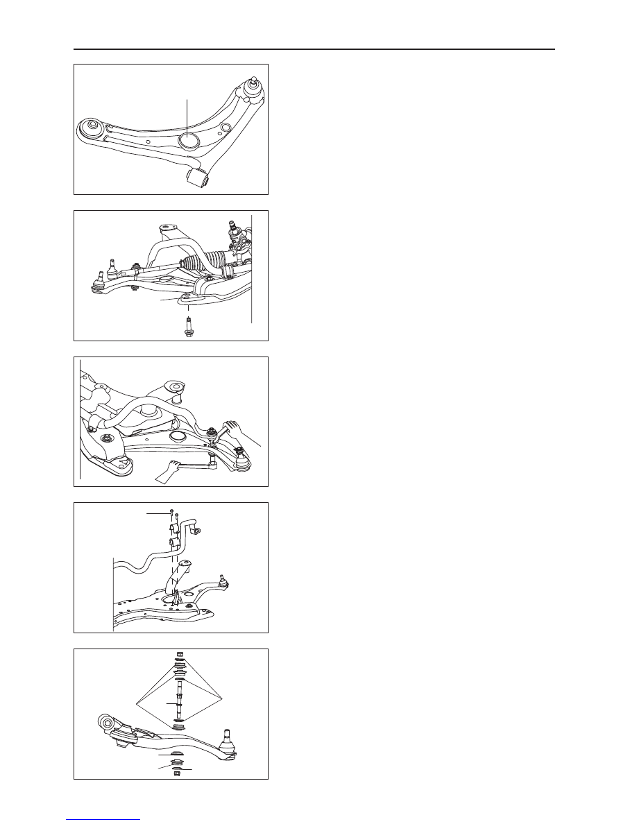
Remark: When removing the subframe's front mounting bolt, 

an extension bar should be inserted through the lower swing 

arm's hole. Positions shown on the left.

5.  Subframe installation.

Installation follows the reverse removal steps.

Caution: Fix the position of the subframe with the 

position  pin,  to  avoid  influencing  the  four  wheels' 

positioning. Location hole is shown on the left: a total 

of two, one on the left and one on the right. 

Stabilizer bar removal and installation

1.  Remove the hanger rod.

Use a M10 open-end wrench to lock the sliding side of the 

hanger rod (slightly higher than center position), screw off 

the hanger rod lock nuts, and remove the hanger rod.

Caution: These are non-metal insert lock nuts, and 

cannot be reused. So please replace them with new 

ones after removal.

2.  Remove the stabilizer bar arm.

Remove the stabilizer bar bracket mounting bolts Q1400830 

(d2=13.5), and take down the bracket and bushing. As shown 

on the left: There are four bolts, two on the left and two on 

the right. 

Tightening torque: 23±3 N·m

3.  Stabilizer bar installation.

Install it by reversing the removal steps, but please pay 

attention to the areas of importance below: 

(a)  During removal, please remember the installation order 

of each of the hanger rod's components, so as to avoid 

improper installation. 

Insert extension bar 

through this hole

This is the subframe 

location hole

Q1400830

Washer

Bushing

Hanger 

rod

Shaft sleeve

Bushing

Washer

79

Suspension System

(b)  The sliding side of the hanger rod should face upward, 

so as to make the operation more convenient. 

Correct Incorrect

GWFLORID Maintenance Manual

80

Lower Swing Arm

Components

Swing arm removal and installation

1.  First, remove the steering knuckle, subframe, and 

stabilizer bar hanger rod. For detailed steps, please 

refer to the removal of the steering knuckle, subframe, 

and stabilizer bar.

2.  Screw off the lower swing arm's front mounting bolt 

Q1401495 (t=4) (M14×1.5) FD with a sleeve. 

Tightening torque: 136±10 N·m

3.  Screw off the lower swing arm's rear mounting bolt 

Q1401280 (M12×1.25) FD with a sleeve.

Tightening torque: 107±10 N·m

Caution: The nuts here are designed to prevent sliding. 

When installing or removing, please do not tighten or 

loosen this part, a sleeve needs to be used to apply 

force onto the bolt. 

Lower swing arm

Subframe

Q1401495

Q1401280

Q1401495

Q1401280

81

Suspension System

4.  Remove the lower swing arm.

Swing the lower swing arm up and down, and pull it out at 

the same time. Force F shown as in the picture. Pull the front 

mount point of the swing arm from the subframe, and then 

take down the lower swing arm.

5.  Lower swing arm installation.

Install it by reversing the removal steps. 

Lower swing arm assembly inspection

1.  Lower swing arm ball stud inspection.

(a)  Check that the ball stud's swing angle is within 50°, 

swings flexibly, and clamping free. 

(b)  Check to see if the ball stud is damaged. 

(c)  Check to see if the ball stud dust cover is damaged and 

replace it if needed. 

Caution: Do not take apart the lower swing arm weld as-

sembly and the lower swing arm ball stud. If the rotation is 

not flexible or if the ball stud is damaged, the entire lower 

swing arm with ball stud assembly must be replaced.

2.  Ball stud dust cover replacement.

Rotate and remove the fastened ball stud dust cover clasp 

with SST, and replace the ball stud dust cover. You can 

reattach the clasp with the same tool. 

3.  Inspect the lower swing arm's large and small shaft sleeve 

for signs of wear.

Clean the large and small shaft sleeve of the lower swing 

arm with water, and inspect for damage, wear, cracks, and 

similar flaws. Replace with new ones if needed. 

4.  Lower swing arm's large shaft sleeve removal, replace-

ment, and press fitting. 

(a)  Before removing, mark two lines on the lower swing 

arm according to the shaft sleeve location, so as to refer 

to the proper location during press fitting. 

Front

Rear

F

SST


Content   ..  18  19  20  21   ..