Ford Galaxy / Ford S-MAX. Manual - part 726
 

  Index      Ford     Ford Galaxy / Ford S-MAX - service repair manual 2006 year


Search            


Content   ..  724  725  726  727   ..


Ford Galaxy / Ford S-MAX. Manual - part 726


GO to H3

.  

No 

REPAIR the circuit(s) in question. TEST the system 
for normal operation. 

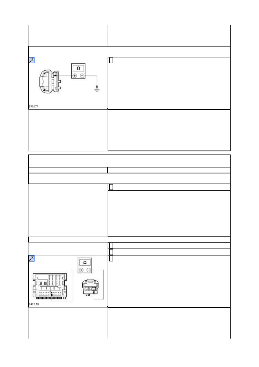
H3: CHECK THE INOPERATIVE TWEETER SPEAKER(S) CIRCUIT FOR SHORT TO 
GROUND

Measure the resistance between the following rear 
tweeter speaker pins, harness side and ground: 

Left-hand side C7ME39 pin 1, circuit VME39A 
(GN/BN).  
Right-hand side C8ME4D pin 1, circuit VME40A 
(BN/WH). 

1 

Is the resistance greater than 10,000 ohms (open 
circuit)? 
Yes 

INSTALL a new tweeter speaker. TEST the system for 
normal operation. 

No 

REPAIR the circuit(s) in question. TEST the system 
for normal operation. 

PINPOINT TEST I : THE AUDIO CONTROL SWITCH IS INOPERATIVE/DOES 
NOT OPERATE CORRECTLY 

TEST CONDITIONS

DETAILS/RESULTS/ACTIONS

I1: CHECK THE AUDIO UNIT OPERATES CORRECTLY USING THE AUDIO UNIT 
CONTROLS

Operate the audio unit using the audio unit controls. 

1 

Does the audio unit operate correctly using the audio unit 
controls? 
Yes 

GO to I2

.  

No 

INSTALL a new audio unit.  
REFER to: Audio Unit (415-01 Information and 
Entertainment System, Removal and Installation). 
TEST the system for normal operation. 

I2: CHECK CIRCUIT VME14A (GY/YE) FOR OPEN

Disconnect Audio Unit C2ME03B. 

1 

Disconnect Clockspring C2LS41. 

2 

Measure the resistance between the audio unit 
C2ME03B pin 6, circuit VME14A (GY/YE) harness side 

and the clockspring C2LS41 pin 11, circuit VME14A 
(GY/YE) harness side. 

3 

Is the resistance less than 1 ohm? 
Yes 

GO to I3

.  

No 

REPAIR the circuit. TEST the system for normal 


operation. 

I3: CHECK CIRCUIT RME24A (BU/WH) FOR OPEN

Measure the resistance between the audio unit 
C2ME03B pin 8, circuit RME24A (BU/WH) harness 

side and the clockspring CME14 pin 2, circuit RME24B 
(BU/WH) harness side. 

1 

Is the resistance less than 1 ohm? 
Yes 

INSTALL a new audio control switch. TEST the system 
for normal operation. If the concern persists, 
INSTALL a new audio unit.  
REFER to: Audio Unit (415-01 Information and 
Entertainment System, Removal and Installation). 

No 

REPAIR the circuit. TEST the system for normal 
operation. 

PINPOINT TEST J : THE CD CHANGER IS INOPERATIVE/DOES NOT 
OPERATE CORRECTLY 

TEST CONDITIONS

DETAILS/RESULTS/ACTIONS

J1: CHECK THE CD CHANGER FOR VOLTAGE

Disconnect CD changer C2ME27. 

1 

Measure the voltage between the CD changer 
C2ME27 pin 1, circuit SBR05AWA (GY/RD), harness 

side and ground. 

2 

Is the voltage greater than 10 volts? 
Yes 

GO to J2

.  

No 

REPAIR circuit SBR05AWA (GY/RD). TEST the system 
for normal operation. 

J2: CHECK THE CD CHANGER FOR GROUND

Measure the resistance between the CD changer 
C2ME27 pin 6, circuit GD135M (BK/GY), harness side 

and ground. 

1 

Is the resistance less than 1 ohm? 
Yes 

GO to J3

.  

No 


REPAIR the circuit. TEST the system for normal 
operation. 

J3: CHECK THE CD CHANGER TO AUDIO UNIT CIRCUIT(S) FOR OPEN

Disconnect Audio Unit C2ME03B. 

1 

Measure the resistance between the following CD 
changer circuits and the audio unit circuit(s): 

CD changer C2ME27 pin 3, circuit VME15B 
(GN/BK), harness side and audio unit C2ME03B pin 
3, circuit VME15A (GN/BK), harness side. 

CD changer C2ME27 pin 8, circuit RME15B 
(VT/GY), harness side and audio unit C2ME03B pin 
9, circuit RME15A (VT/GY), harness side. 

CD changer C2ME27 pin 4, circuit VME16B 
(GY/RD), harness side and audio unit C2ME03B pin 
4, circuit RME16A (GY/RD), harness side. 

CD changer C2ME27 pin 9, circuit RME16B 
(YE/GY), harness side and audio unit C2ME03B pin 
10, circuit RME16A (YE/GY), harness side. 

2 

Are the resistances less than 1 ohm? 
Yes 

INSTALL a new CD changer. TEST the system for 
normal operation. 

No 

REPAIR the circuits as necessary. TEST the system 
for normal operation. If the concern persists, 
INSTALL a new audio unit.  

PINPOINT TEST K : THE AUXILIARY INPUT DEVICE IS 
INOPERATIVE/DOES NOT OPERATE CORRECTLY 

TEST CONDITIONS

DETAILS/RESULTS/ACTIONS

K1: CHECK THE OPERATION OF THE AUXILIARY INPUT DEVICE

Operate the auxiliary input device outside of the 
vehicle. 

1 

Does the auxiliary input device operate outside of the 
vehicle? 
Yes 

GO to K3

.  

No 

REFER to the auxiliary input device Owner Guide. 

K2: CHECK THE AUXILIARY INPUT DEVICE CONNECTOR

Check the auxiliary input device connector for signs 
of damage or debris. 

1 

Is the auxiliary input device connector free of damage 
and debris? 
Yes 

GO to K3

.  

No 

INSTALL a new auxiliary input device connector. TEST 
the system for normal operation. 

K3: CHECK CIRCUIT VME37A (BU/RD) FOR OPEN

Disconnect Audio Unit C2ME03C. 

1 

Measure the resistance between the audio unit 
C2ME03C pin 5, circuit VME37A (BU/RD), harness 

side and auxiliary input device C2ME37 pin 4, circuit 

2 


VME37A (BU/RD), harness side. 

Is the resistance less than 1 ohm? 
Yes 

GO to K4

.  

No 

REPAIR circuit VME37A (BU/RD). TEST the system for 
normal operation. 

K4: CHECK CIRCUIT VME38A (BN/RD) FOR OPEN

Measure the resistance between the audio unit 
C2ME03C pin 11, circuit VME38A (BN/RD), harness 

side and auxiliary input device C2ME37 pin 1, circuit 
VME38A (BN/RD), harness side. 

1 

Is the resistance less than 1 ohm? 
Yes 

GO to K5

.  

No 

REPAIR circuit VME38A (BN/RD). TEST the system for 
normal operation. 

K5: CHECK CIRCUIT DME37G (OG/GN) FOR GROUND

Measure the resistance between the audio unit 
C2ME03C pin 6, circuit DME37G (OG/GN), harness 

side and ground. 

1 

Is the resistance less than 1 ohm? 
Yes 

INSTALL a new audio unit. TEST the system for 
normal operation. 

No 

REPAIR circuit DME37G (OG/GN). TEST the system 
for normal operation. 

PINPOINT TEST L : THE DIGITAL VERSATILE DISC (DVD) PLAYER IS 
INOPERATIVE/DOES NOT OPERATE CORRECTLY 

TEST CONDITIONS

DETAILS/RESULTS/ACTIONS

L1: CHECK THE DVD PLAYER FOR POWER

Disconnect DVD Player C2MR-A. 

1 

Measure the voltage between the DVD player C2MR-A 
pin 4, circuit C_SBR05D (GY/RD), harness side and 

2 


Content   ..  724  725  726  727   ..