Ford Galaxy / Ford S-MAX. Manual - part 725
 

  Index      Ford     Ford Galaxy / Ford S-MAX - service repair manual 2006 year


Search            


Content   ..  723  724  725  726   ..


Ford Galaxy / Ford S-MAX. Manual - part 725


Measure the resistance between the following affected 
speaker pins, component side. 

(Front speakers) pin 1 and pin 4.  
(Third row speakers) pins 1 and 2 (if equipped).  
(Rear speakers) pin 1 and pin 4. 

2 

Is the resistance approximately 4.0 ohms? 
Yes 

GO to F2

.  

No 

INSTALL a new speaker. TEST the system for normal 
operation. 

F2: CHECK THE INOPERATIVE SPEAKER(S) CONNECTOR INPUT CIRCUIT(S)

Disconnect Audio Unit C2ME03D. 

1 

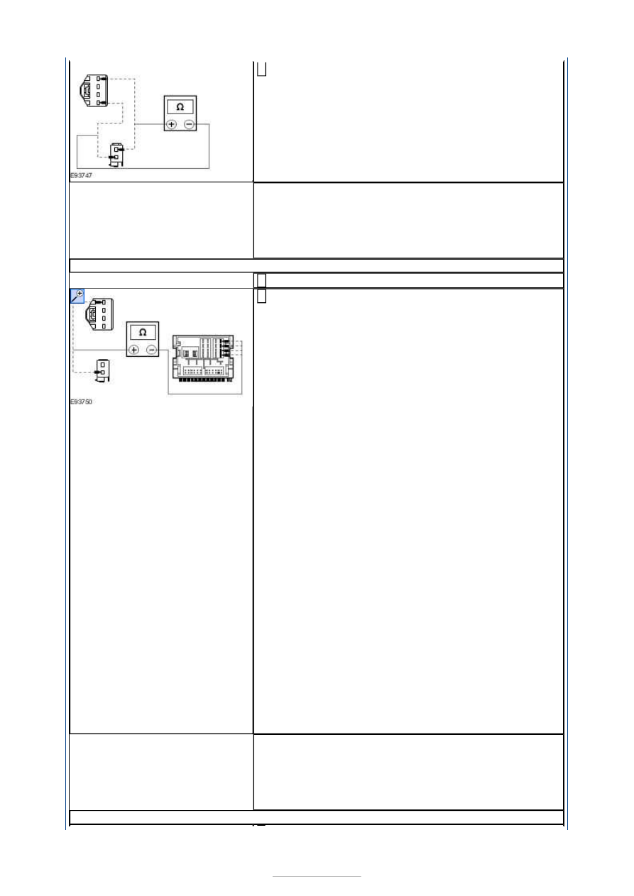
Measure the resistance between the following audio 
unit C2ME03D pins, harness side and the inoperative 

speaker(s) input circuit(s), harness side: 

Left-hand drive vehicles (Left front speaker) 
C5ME07 pin 1, circuit VME07A (WH) to C2ME03D pin 
3, circuit VME07C (WH). 

Left-hand drive vehicles (Right front speaker) 
C6ME10 pin 1, circuit VME10A (WH/VT) to CME03D 
pin 2, circuit VME10C (WH/VT). 

Right-hand drive vehicles(Left front speaker) 
C6ME10 pin 1, circuit VME10A (WH/VT) to C2ME03D 
pin 3, circuit VME07C (WH). 

Right-hand drive vehicles(Right front speaker) 
C5ME07 pin 1, circuit VME07A (WH) to C2ME03D pin 
2, circuit VME10C (WH/VT). 

(Left third row speaker) C4ME09 pin 1, circuit 
VME09D (BN/GN) to C2ME03D pin 4, circuit VME09C 
(BN/GN). 

(Right third row speaker) C4ME12 pin 1, circuit 
VME12B (BN/WH) to C2ME03D pin 1, circuit VME12C 
(BN/WH). 

(Left rear speaker) C7ME09 pin 1, circuit VME09A 
(BN/GN) to C2ME03D pin 4, circuit VME09C (BN/GN). 

(Right rear speaker) C8ME12 pin 1, circuit VME12A 
(BN/WH) to C2ME03D pin 1, circuit VME12C 
(BN/WH). 

2 

Is the resistance less than 1 ohm? 
Yes 

GO to F3

.  

No 

REPAIR the circuit(s) in question. TEST the system for 
normal operation. 

F3: CHECK THE INOPERATIVE SPEAKER(S) CONNECTOR OUTPUT CIRCUIT(S)


Measure the resistance between the following audio 
unit C2ME03D pins, harness side and the inoperative 

speaker(s) output circuit(s), harness side: 

Left-hand drive vehicles (Left front speaker) 
C5ME07 pin 4, circuit RME07A (WH/BN) to C2ME03D 
pin 7, circuit RME07C (WH/BN). 

Left-hand drive vehicles (Right front speaker) 
C6ME10 pin 4, circuit RME10A (WH/OG) to CME03D 
pin 6, circuit RME10C (WH/OG). 

Right-hand drive vehicles(Left front speaker) 
C6ME10 pin 4, circuit RME10A (WH/OG) to C2ME03D 
pin 7, circuit RME07C (WH/OG). 

Right-hand drive vehicles(Right front speaker) 
C5ME07 pin 4, circuit RME07A (WH/OG) to C2ME03D 
pin 6, circuit RME10C (WH/OG). 

(Left third row speaker) C4ME09 pin 2, circuit 
RME09D (BN/YE) to C2ME03D pin 8, circuit RME09C 
(BN/YE). 

(Right third row speaker) C4ME12 pin 2, circuit 
RME12B (BN/BU) to C2ME03D pin 5, circuit RME12C 
(BN/YE). 

(Left rear speaker) C7ME09 pin 4, circuit RME09A 
(BN/YE) to C2ME03D pin 8, circuit RME09C (BN/YE). 

(Right rear speaker) C8ME12 pin 4, circuit RME12A 
(BN/BU) to C2ME03D pin 5, circuit RME12C (BN/BU). 

1 

Is the resistance less than 1 ohm? 
Yes 

GO to F4

.  

No 

REPAIR the circuit(s) in question. TEST the system for 
normal operation. 

F4: CHECK THE INOPERATIVE SPEAKER(S) CIRCUIT FOR SHORT TO GROUND

Measure the resistance between the following 
inoperative speaker(s) input circuit(s), harness side 

and ground: 

Left-hand drive vehicles (Left front speaker) 
C5ME07 pin 1, circuit VME07A (WH). 

Left-hand drive vehicles (Right front speaker) 
C6ME10 pin 1, circuit VME10A (WH/VT). 

Right-hand drive vehicles(Left front speaker) 
C6ME10 pin 1, circuit VME10A (WH/VT). 

Right-hand drive vehicles(Right front speaker) 
C5ME07 pin 1, circuit VME07A (WH). 

(Left third row speaker) C4ME09 pin 1, circuit 
VME09D (BN/GN). 

1 


(Right third row speaker) C4ME12 pin 1, circuit 
VME12B (BN/WH). 

(Left rear speaker) C7ME09 pin 1, circuit VME09A 
(BN/GN). 

(Right rear speaker) C8ME12 pin 1, circuit VME12A 
(BN/WH). 

Is the resistance greater than 10,000 ohms (open circuit)? 
Yes 

INSTALL a new speaker. TEST the system for normal 
operation.  

No 

REPAIR the circuit(s) in question. TEST the system for 
normal operation. 

PINPOINT TEST G : NO SOUND FROM ONE OR MORE OF THE FRONT 
TWEETER SPEAKERS (NOT ALL SPEAKERS) 

TEST CONDITIONS

DETAILS/RESULTS/ACTIONS

G1: CHECK THE INOPERATIVE SPEAKER(S) CONNECTOR INPUT CIRCUIT(S)

Disconnect Affected Front Tweeter Speaker. 

1 

Disconnect Audio Unit C2ME03D. 

2 

Measure the resistance between the following audio 
unit C2ME03D pins, harness side and the inoperative 

front tweeter speaker(s) input circuit(s), harness 
side: 

Left-hand side C2ME03D pin 3, circuit VME07D 
(WH) to C5MED8 pin 1, circuit VME07D (WH).  
Right-hand side C2ME03D pin 2, circuit VME10D 
(WH/VT) to C6ME11 pin 1, circuit VME10D 
(WH/VT). 

3 

Is the resistance less than 1 ohm? 
Yes 

GO to G2

.  

No 

REPAIR the circuit(s) in question. TEST the system 
for normal operation. 

G2: CHECK THE INOPERATIVE SPEAKER(S) CONNECTOR OUTPUT CIRCUIT(S)

Measure the resistance between the following audio 
unit C2ME03D pins, harness side and the inoperative 

front tweeter speaker(s) output circuit(s), harness 
side: 

Left-hand side C2ME03D pin 7, circuit RME07D 
(WH/BN) to C5MED8 pin 3, circuit RME07D 
(WH/BN).  
Right-hand side C2ME03D pin 6, circuit RME10D 
(WH/OG) to C6ME11 pin 3, circuit RME10D 
(WH/OG). 

1 

Is the resistance less than 1 ohm? 
Yes 

GO to G3

.  

No 

REPAIR the circuit(s) in question. TEST the system 
for normal operation. 

G3: CHECK THE INOPERATIVE TWEETER SPEAKER(S) CIRCUIT FOR SHORT TO 


GROUND

Measure the resistance between the following 
inoperative front tweeter speaker(s) input circuit(s), 

harness side and ground: 

Left-hand side C5MED8 pin 1, circuit VME07D 
(WH).  
Right-hand side C6ME11 pin 1, circuit VME10D 
(WH/VT). 

1 

Is the resistance greater than 10,000 ohms (open 
circuit)? 
Yes 

INSTALL a new tweeter speaker. TEST the system for 
normal operation. 

No 

REPAIR the circuit(s) in question. TEST the system 
for normal operation. 

PINPOINT TEST H : NO SOUND FROM ONE OR MORE OF THE REAR 
TWEETER SPEAKERS (NOT ALL SPEAKERS) 

TEST CONDITIONS

DETAILS/RESULTS/ACTIONS

H1: CHECK THE INOPERATIVE SPEAKER(S) CONNECTOR INPUT CIRCUIT(S)

Disconnect Affected Rear Tweeter Speaker. 

1 

Disconnect Rear Speaker On Affected Rear Tweeter 
Speaker Side C7ME09 (Left-hand side) C8ME12 

(Right-hand side). 

2 

Measure the resistance between the following rear 
tweeter speaker pins, harness side and the 

inoperative tweeter speaker(s) input circuit(s), 
harness side: 

Left-hand side C7ME09 pin 2, circuit VME39A 
(GN/BN), harness side and C7ME39 pin 1, circuit 
VME39A (GN/BN), harness side.  
Right-hand side C8ME12 pin 2, circuit VME40A 
(BN/WH), harness side and C8ME4D pin 1, circuit 
VME40A (BN/WH), harness side. 

3 

Is the resistance less than 1 ohm? 
Yes 

GO to H2

.  

No 

REPAIR the circuit(s) in question. TEST the system 
for normal operation. 

H2: CHECK THE INOPERATIVE SPEAKER(S) CONNECTOR OUTPUT CIRCUIT(S)

Measure the resistance between the following rear 
tweeter speaker pins, harness side and the 

inoperative tweeter speaker(s) input circuit(s), 
harness side: 

Left-hand side C7ME09 pin 3, circuit RME39A 
(OG/WH), harness side and C7ME39 pin 3, circuit 
RME39A (OG/WH), harness side.  
Right-hand side C8ME12 pin 3, circuit RME40A 
(OG/VT), harness side and C8ME4D pin 3, circuit 
RME40A (OG/VT), harness side. 

1 

Is the resistance less than 1 ohm? 
Yes 


Content   ..  723  724  725  726   ..