Ford Galaxy / Ford S-MAX. Manual - part 75
 

  Index      Ford     Ford Galaxy / Ford S-MAX - service repair manual 2006 year


Search            


Content   ..  73  74  75  76   ..


Ford Galaxy / Ford S-MAX. Manual - part 75


Disconnect Rear Junction Box C4BR02. 

1 

Measure the resistance between the: 

EPB module C4CB01 pin 13, circuit C_SBR03A 
(BU/RD), harness side and the rear junction box 
C4BR02-C pin 304, circuit C_SBR03A (BU/RD).  
EPB module C4CB01 pin 15, circuit C_SBR02A 
(YE/RD), harness side and the rear junction box 
C4BR02-C pin 303, circuit C_SBR02A (YE/RD). 

2 

Are the resistances less than 2 ohms? 
Yes 

INSTALL a new EPB module.  
REFER to: Parking Brake Module (206-05 Parking 
Brake and Actuation, Removal and Installation). 
REPEAT the self-test, CLEAR the DTCs. 

No 

REPAIR circuit C_SBR02A (YE/RD) or circuit 
C_SBR03A (BU/RD). REPEAT the self-test, CLEAR the 
DTCs. 

PINPOINT TEST AB : DTC U3003.62: BATTERY VOLTAGE / DTC U3006.16: 
BATTERY VOLTAGE (LOW OR HIGH) 

TEST CONDITIONS

DETAILS/RESULTS/ACTIONS

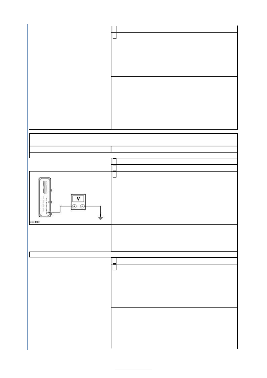
AB1: CHECK THE EPB MODULE MOTOR SUPPLY CIRCUIT

Disconnect EPB Module C4CB01. 

1 

Ignition switch in position II. 

2 

Measure the voltage between the: 

EPB module C4CB01 pin 13, circuit C_SBR03A 
(BU/RD), harness side and ground.  
EPB module C4CB01 pin 15, circuit C_SBR02A 
(YE/RD), harness side and ground. 

3 

Are the voltages greater than 10 volts? 
Yes 

GO to AB2

.  

No 

GO to AB3

.  

AB2: CHECK THE EPB MODULE MOTOR SUPPLY CIRCUIT IMPEDANCE

Disconnect Rear Junction Box C4BR02. 

1 

Measure the resistance between the: 

EPB module C4CB01 pin 13, circuit C_SBR03A 
(BU/RD), harness side and the rear junction box 
C4BR02-C pin 304, circuit C_SBR03A (BU/RD).  
EPB module C4CB01 pin 15, circuit C_SBR02A 
(YE/RD), harness side and the rear junction box 
C4BR02-C pin 303, circuit C_SBR02A (YE/RD). 

2 

Are the resistances less than 2 ohms? 
Yes 

INSTALL a new EPB module.  
REFER to: Parking Brake Module (206-05 Parking 
Brake and Actuation, Removal and Installation). 
REPEAT the self-test, CLEAR the DTCs. 

No 


REPAIR circuit C_SBR02A (YE/RD) or circuit 
C_SBR03A (BU/RD). REPEAT the self-test, CLEAR the 
DTCs. 

AB3: CHECK THE EPB MODULE MOTOR SUPPLY

Measure the voltage between the: 

EPB module C4CB01 pin 13, circuit C_SBR03A 
(BU/RD), harness side and ground.  
EPB module C4CB01 pin 15, circuit C_SBR02A 
(YE/RD), harness side and ground. 

1 

Is any voltage present? 
Yes 

Check the charging system.  
REFER to: Charging System (414-00 Charging 
System - General Information, Diagnosis and 
Testing). 
REPEAT the self-test, CLEAR the DTCs. 

No 

REPAIR circuit C_SBR02A (YE/RD) or circuit 
C_SBR03A (BU/RD). REPEAT the self-test, CLEAR the 
DTCs. 

PINPOINT TEST AC : DTC U300A.62: IGNITION CROSS CHECK FAULT 

TEST CONDITIONS

DETAILS/RESULTS/ACTIONS

AC1: CHECK THE EPB MODULE SUPPLY CIRCUIT

Disconnect EPB Module C4CB01. 

1 

Ignition switch in position II. 

2 

Measure the voltage between the EPB module 
C4CB01 pin 22, circuit CBP03B (GY), harness side 

and ground. 

3 

Is the voltage greater than 10 volts? 
Yes 

GO to AC2

.  

No 

REPAIR circuit CBP03B (GY). REPEAT the self-test, 
CLEAR the DTCs. 

AC2: CHECK THE EPB MODULE SUPPLY SWITCH CIRCUIT

Ignition switch in position 0. 

1 

Measure the voltage between the EPB module 
C4CB01 pin 22, circuit CBP03B (GY), harness side 

and ground. 

2 


Is any voltage present? 
Yes 

REPAIR circuit CBP03B (GY). REPEAT the self-test, 
CLEAR the DTCs. 

No 

REPEAT the self-test, CLEAR the DTCs. If the DTC 
remains, INSTALL a new EPB module.  
REFER to: Parking Brake Module (206-05 Parking 
Brake and Actuation, Removal and Installation). 
REPEAT the self-test, CLEAR the DTCs. 

PINPOINT TEST AD : DTC U300A.86: IGNITION CROSS CHECK FAULT 

TEST CONDITIONS

DETAILS/RESULTS/ACTIONS

AD1: CHECK THE EPB MODULE KEY IN CIRCUIT

Disconnect EPB Module C4CB01. 

1 

Insert the ignition key. 

2 

Measure the voltage between the EPB module 
C4CB01 pin 4, circuit CCB28A (GY/BN), harness side 

and ground. 

3 

Is the voltage greater than 10 volts? 
Yes 

GO to AD2

.  

No 

REPAIR circuit CCB28A (GY/BN). REPEAT the self-
test, CLEAR the DTCs. 

AD2: CHECK THE EPB MODULE KEY OUT CIRCUIT

Remove the ignition key. 

1 

Measure the voltage between the EPB module 
C4CB01 pin 4, circuit CCB28A (GY/BN), harness side 

and ground. 

2 

Is any voltage present? 
Yes 

REPAIR circuit CCB28A (GY/BN). REPEAT the self-
test, CLEAR the DTCs. 

No 

REPEAT the self-test, CLEAR the DTCs. If the DTC 
remains, INSTALL a new EPB module.  
REFER to: Parking Brake Module (206-05 Parking 
Brake and Actuation, Removal and Installation). 
REPEAT the self-test, CLEAR the DTCs. 


Parking Brake and Actuation - Electronic 
Parking Brake (EPB) Release Using a 
Special Tool

S-MAX/Galaxy 2006.5 (02/2006-)


Print


General Procedures 

Special Tool(s) 

206-012 
Retractor, Rear Brake Caliper Piston 

1.  

2. Special Tool(s): 

206-012


3. Torque: 35 Nm 


Content   ..  73  74  75  76   ..