Ford Galaxy / Ford S-MAX. Manual - part 73
 

  Index      Ford     Ford Galaxy / Ford S-MAX - service repair manual 2006 year


Search            


Content   ..  71  72  73  74   ..


Ford Galaxy / Ford S-MAX. Manual - part 73


side and the EPB module C4CB01 pin 29, circuit 
CCB17A (BU/GN), harness side 

Is the resistance greater than 10,000 ohms? 
Yes 

REPEAT the self-test, CLEAR the DTCs. If the DTC 
remains 

GO to U2

.  

No 

GO to U2

.  

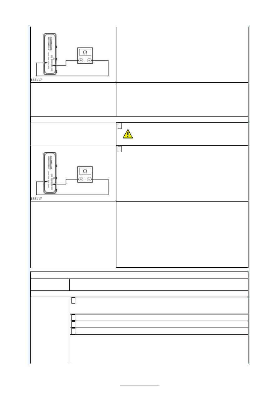
U2: CHECK THE PARKING BRAKE RELEASE ACTUATOR CIRCUITS

Disconnect Parking Brake Release Actuator C4CB06. 

CAUTION: Make sure that the area around the 

component is clean and free of foreign material. 

1 

Measure the resistance between the EPB module 
C4CB01 pin 14, circuit CCB16B (WH/VT), harness 

side and the EPB module C4CB01 pin 29, circuit 
CCB17A (BU/GN), harness side 

2 

Is the resistance greater than 10,000 ohms? 
Yes 

INSTALL a new parking brake release actuator.  
REFER to: Parking Brake Release Actuator (206-05 
Parking Brake and Actuation, Removal and 
Installation). 
REPEAT the self-test, CLEAR the DTCs. 

No 

REPAIR circuit CCB18A (YE/GY), or circuit CCB18B 
(YE/GY), or circuit CCB19A (GN/BN), or circuit 
CCB19B (GN/BN). REPEAT the self-test, CLEAR the 
DTCs. 

PINPOINT TEST V : DTC C2008.1D: LEFT ACTUATOR FAULT 

TEST 

CONDITIONS

DETAILS/RESULTS/ACTIONS

V1: CHECK THE BRAKE DISC AND PADS

Remove the wheel and tire.  
REFER to: Wheel and Tire (204-04 Wheels and Tires, Removal and 

Installation). 

1 

Connect WDS. 

2 

Select 'Service' mode and retract brake pads. 

3 

CHECK the brake disc and brake pads. 

4 

Are the brake disc and brake pads OK? 
Yes 

REFER to: Parking Brake Release Actuator (206-05 Parking Brake and 
Actuation, Removal and Installation). 

No 


REFER to: Brake Pads - Vehicles With: Electronic Parking Brake (206-04 
Rear Disc Brake, Removal and Installation). 

PINPOINT TEST W : DTC P061E: INTERNAL CONTROL MODULE BRAKE 
SIGNAL PERFORMANCE 

TEST CONDITIONS

DETAILS/RESULTS/ACTIONS

W1: CHECK THE WDS IS COMMUNICATING THROUGH THE DATA LINK CONNECTOR 
(DLC)

Ignition switch in position II. 

1 

Select an alternative system to check the DLC. 

2 

Is WDS able to communicate with the selected system? 
Yes 

GO to W2

.  

No 

CHECK the DLC. For additional information, REFER to 
the Wiring Diagrams. 

W2: CHECK THE POWERTRAIN CONTROL MODULE (PCM) CIRCUIT

Check for PCM DTCs. 

1 

Is WDS able to communicate with the PCM? 
Yes 

CLEAR any PCM DTCs, REFER to WDS, then 

GO to 

W3

.  

No 

CHECK the PCM circuits.  
REFER to: 

Communications Network

 (418-00 Module 

Communications Network, Diagnosis and Testing). 

W3: CHECK THE ABS MODULE CIRCUIT

Check for ABS DTCs. 

1 

Is WDS able to communicate with the ABS module? 
Yes 

CLEAR any ABS DTCs, REFER to WDS, then 

GO to 

W4

.  

No 

REPAIR circuit VDB04S (WH/BU) or circuit VDB05S 
(WH). REPEAT the self-test, CLEAR the DTCs. 

W4: CHECK THE CJB

Check for CJB DTCs. 

1 

Is WDS able to communicate with the CJB? 
Yes 

CLEAR any CJB DTCs, REFER to WDS, then 

GO to W5

. 

No 

REPAIR circuit VDB04Y (WH/BU) or circuit VDB05AB 
(WH). REPEAT the self-test, CLEAR the DTCs. 

W5: CHECK THE EPB MODULE CIRCUIT

1 

Is WDS able to communicate with the EPB module? 
Yes 

GO to W6

.  

No 

REPAIR circuit VDB04N (WH/BU) or circuit VDB05E 
(WH). REPEAT the self-test, CLEAR the DTCs. 

W6: CHECK THE CENTRAL JUNCTION BOX (CJB) CIRCUIT

Disconnect EPB Module C4CB01. 

1 

Disconnect CJB C1BP02-C. 

2 

Measure the resistance between the: 

EPB module C4CB01 pin 16, circuit VDB04N 

3 

(WH/BU), harness side and the CJB C1BP02-C pin 
47, circuit VDB04Y (WH/BU), harness side.  
EPB module C4CB01 pin 17, circuit VDB05E (WH), 
harness side and the CJB C1BP02-C pin 48, circuit 
VDB05AB (WH), harness side. 

Are the resistances less than 5 ohms? 
Yes 

REPEAT the self-test, CLEAR the DTCs. 

No 

REPAIR circuit VDB04Y (WH/BU) or circuit VDB05AB 
(WH). REPEAT the self-test, CLEAR the DTCs. 

PINPOINT TEST X : DTC U0001: HIGH SPEED CAN BUS 

TEST CONDITIONS

DETAILS/RESULTS/ACTIONS

X1: CHECK THE CAN BUS FOR A SHORT CIRCUIT

Disconnect EPB Module C4CB01. 

1 

Measure the resistance between the EPB module 
C4CB01 pin 16, circuit VDB04N (WH/BU), harness 

side and the EPB module C4CB01 pin 17, circuit 
VDB05E (WH), harness side. 

2 

Is the resistance less than 5 ohms? 
Yes 

REPAIR circuit VDB04N (WH/BU) or circuit VDB05E 
(WH). REPEAT the self-test, CLEAR the DTCs. 

No 

GO to X2

.  

X2: CHECK THE CAN HIGH BUS CIRCUIT FOR A SHORT TO GROUND

Measure the resistance between the EPB module 
C4CB01 pin 16, circuit VDB04N (WH/BU), harness 

side and ground. 

1 

Is the resistance less than 5 ohms? 
Yes 

REPAIR circuit VDB04N (WH/BU). REPEAT the self-
test, CLEAR the DTCs. 

No 

GO to X3

.  

X3: CHECK THE CAN LOW BUS CIRCUIT FOR A SHORT TO POWER

Ignition switch in position II. 

1 

Measure the voltage between the EPB module 
C4CB01 pin 17, circuit VDB05E (WH), harness side 

and ground. 

2 


Is any voltage present? 
Yes 

REPAIR circuit VDB05E (WH). REPEAT the self-test, 
CLEAR the DTCs. 

No 

GO to X4

.  

X4: CHECK THE CAN BUS CIRCUIT CONTINUITY

Ignition switch in position 0. 

1 

Measure the resistance between the: 

EPB module C4CB01 pin 16, circuit VDB04N 
(WH/BU), harness side and the DLC C3DB04 pin 6, 
circuit VDB04L (WH/BU), harness side.  
EPB module C4CB01 pin 17, circuit VDB05E (WH), 
harness side and the DLC C3DB04 pin 14, circuit 
VDB05Z (WH), harness side. 

2 

Are the resistances less than 5 ohms? 
Yes 

INSTALL a new EPB module.  
REFER to: Parking Brake Module (206-05 Parking 
Brake and Actuation, Removal and Installation). 
REPEAT the self-test, CLEAR the DTCs. 

No 

REPAIR circuit VDB04N (WH/BU) or circuit VDB05E 
(WH). REPEAT the self-test, CLEAR the DTCs. 

PINPOINT TEST Y : DTC U2002.62/92: EPB SWITCH FAULT 

TEST CONDITIONS

DETAILS/RESULTS/ACTIONS

Y1: CHECK THE EPB SWITCH CIRCUITS FOR A SHORT TO POWER

Disconnect EPB Module C4CB01. 

1 

Disconnect EPB Switch C3CB09. 

2 

Ignition switch in position II. 

3 

Measure the voltage between the: 

EPB module C4CB01 pin 9, circuit CCB23A 
(VT/GN), harness side and ground.  
EPB module C4CB01 pin 10, circuit CCB25A (BN), 
harness side and ground.  
EPB module C4CB01 pin 11, circuit CCB21A 
(GN/VT), harness side and ground.  
EPB module C4CB01 pin 18, circuit CCB22A 
(WH/BN), harness side and ground.  
EPB module C4CB01 pin 19, circuit CCB24A 
(WH/OG), harness side and ground.  
EPB module C4CB01 pin 20, circuit CCB20A 
(BU/WH), harness side and ground. 

4 


Content   ..  71  72  73  74   ..