Ford F150 Pickup. Instruction - part 687
amps (all others), with engine at 2000 RPM. Go to next step.
2. Turn A/C system on. Turn blower speed to high. Turn headlights on to high beams. Voltage should
increase a minimum of .5 volt. If voltage is as specified, system is operating properly at this time. If
voltage is not as specified, perform GENERATOR NO-LOAD TEST .
GENERATOR NO-LOAD TEST
Switch tester to voltmeter function. Connect voltmeter positive lead to B+ terminal on generator and negative
lead to ground. Turn all electrical accessories off. Start and run engine up to 2000 RPM. Read voltmeter when
voltage stabilizes. Voltage should be 13-15 volts. If voltage is not as specified, go to SYMPTOM INDEX table
under SYSTEM TESTS.
SYSTEM TESTS
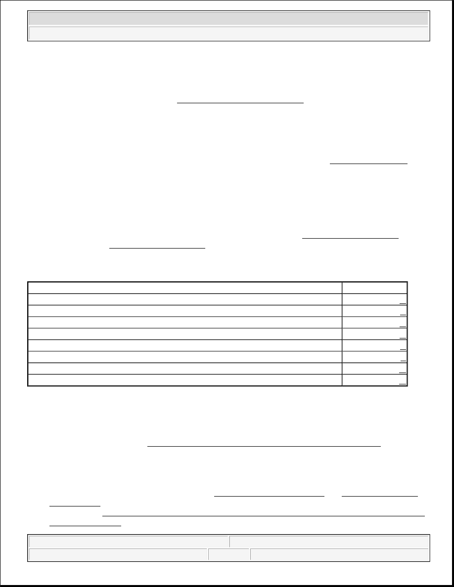
SYMPTOM INDEX
TEST A: BATTERY IS DISCHARGED OR VOLTAGE IS LOW
1. Check The Battery Condition
Test battery condition. See BATTERY TEST WITH DIGITAL BATTERY ANALYZER under ON-
VEHICLE TESTING. If battery is okay, go to next step. If battery is not okay, replace battery.
2. Check The Generator Output
Perform generator load and no-load tests. See GENERATOR LOAD TEST and GENERATOR NO-
LOAD TEST under ON-VEHICLE TESTING. If generator is okay, go to next step. If generator is not
okay, perform TEST B: WARNING INDICATOR IS ON WITH ENGINE RUNNING, SYSTEM IS
NOT CHARGING .
CAUTION: When battery is disconnected, vehicle computer and memory systems
may lose memory data. Driveability problems may exist until computer
systems have completed a relearn cycle. See COMPUTER RELEARN
PROCEDURES - FORD article in GENERAL INFORMATION before
disconnecting battery.
Symptom
Perform Test
Battery Is Discharged Or Voltage Is Low
A
Warning Indicator Is On With Engine Running, System Is Not Charging
B
System Overcharges (Greater Than 15.5 Volts)
C
Warning Indicator Is On With Engine Running, System Is Charging
D
Warning Indicator Is Off With Ignition On
E
Warning Indicator Flickers Or Operates Intermittently
F
Generator Noisy
G
Radio Interference
H
2003 Ford Pickup F150
2003 STARTING & CHARGING SYSTEMS Generators & Regulators - F150 Pickup