Ford F150 Pickup. Instruction - part 646


  Index      Ford     Ford F150 Pickup - service and repair instruction 2003 year


Search            copyright infringement  


Content   ..  644  645  646  647   ..


Ford F150 Pickup. Instruction - part 646


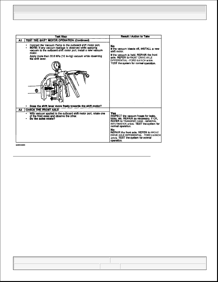
Fig. 23: Pinpoint Test A: Front Axle Will Not Engage Step (A1 Cont. & A2) 
Courtesy of FORD MOTOR CO. 

PINPOINT TEST B: FRONT AXLE WILL NOT DISENGAGE 


2003 Ford Pickup F150 

2003 GENERAL INFORMATION Driveline System - General Information - F150 Pickup


Fig. 24: Pinpoint Test B: Front Axle Will Not Disengage Step (B1) 
Courtesy of FORD MOTOR CO. 

Fig. 25: Pinpoint Test B: Front Axle Will Not Disengage Step (B2) 
Courtesy of FORD MOTOR CO. 

Component Tests 

Driveline Vibration 

WARNING:

The electrical power to the air suspension system must be shut off prior 
to hoisting, jacking or towing an air suspension vehicle. This can be 
accomplished by turning off the air suspension switch. Failure to do so 
can result in unexpected inflation or deflation of the air springs, which 
can result in shifting of the vehicle during these operations.


2003 Ford Pickup F150 

2003 GENERAL INFORMATION Driveline System - General Information - F150 Pickup


Driveline vibration exhibits a higher frequency and lower amplitude than does high-speed shake.

Driveline vibration is directly related to the speed of the vehicle and is usually noticed at various speed ranges. 
Driveline vibration can be perceived as a tremor in the floorpan or is heard as a rumble, hum, or boom. 
Driveline vibration can exist in all drive modes, but may exhibit different symptoms depending upon whether 
the vehicle is accelerating, decelerating, floating, or coasting. Check the driveline angles if the vibration is 
particularly noticeable during acceleration or deceleration, especially at lower speeds. Driveline vibration can 
be duplicated by supporting the axle upon a hoist or upon jack stands, though the brakes may need to be applied 
lightly in order to simulate road resistance. 

1. Raise the vehicle promptly after road testing. Use a twin-post hoist or jack stands to prevent tire flat-

spotting. Engage the drivetrain and accelerate to the observed road test speed to verify the presence of the 
vibration. If the vibration is not evident, check the non-driving wheels with a wheel balancer to rule out 
imbalance as a possible cause. If required, balance the non-driving wheels and repeat the road test. If the 
vibration is still evident, proceed to Step 2.  

2. Mark the relative position of the drive wheels to the wheel bolts. Remove the wheels. Install all the wheel 

nuts in the reversed position and repeat the road speed acceleration. If the vibration is gone, refer to the 
tire and wheel runout procedure in WHEELS & TIRES - F150 PICKUP . If the vibration persists, 
proceed to Step 3.  

3. Inspect the driveshaft(s) for signs of physical damage, missing balance weight, undercoating, incorrect 

seating, wear and binding universal joints. Clean the driveshaft and install new universal joints or the 
driveshaft if damaged. Check the index marks (paint spots) on the rear of the driveshaft and pinion flange. 
If these marks are more than one-quarter turn apart, disconnect the driveshaft and re-index to align the 
marks as closely as possible. After any corrections are made, recheck for vibration at the road test speed. 
If the vibration is gone, reinstall the wheels and road test. If the vibration persists, proceed to Step 4.  

4. Raise the vehicle on a hoist and remove the wheels. Rotate the driveshaft by turning the axle and measure 

the runout at the front, the center, and the rear of the driveshaft with the indicator. If the runout exceeds 
0.89 mm (0.035 inch) at the front or center, a new driveshaft must be installed. If the front and center are 
within this limit, but the rear runout is not, mark the rear runout high point and proceed to Step 5. If the 
runout is within the limits at all points, proceed to Step 7 . 


2003 Ford Pickup F150 

2003 GENERAL INFORMATION Driveline System - General Information - F150 Pickup


Fig. 26: Raising Vehicle On A Hoist And Remove Wheels 
Courtesy of FORD MOTOR CO. 

5. Scribe alignment marks on the driveshaft and the axle pinion flange. Disconnect the driveshaft, rotate it 

one-half turn, and reconnect it. Circular axle pinion flanges can be turned in one-quarter increments to 
fine tune the runout condition; half-round pinion flanges are limited to two positions. Check the runout at 
the rear of the driveshaft. If it is still over 0.89 mm (0.035 inch), mark the high point and proceed to Step 
6. If the runout is no longer excessive, check for vibration at the road test speed. If vibration is still 
present, re-index the driveshaft slip-yoke on the transmission output shaft one-half turn and road test the 
vehicle. If the vibration persists, proceed to Step 7 .  

6. Excessive driveshaft runout may originate in the driveshaft itself or in the pinion flange. To determine 

which, compare the two high points marked in Steps 4 and 5. If the marks are close together, within about 
25 mm (1 inch), a new shaft must be installed and the vehicle road tested. 

NOTE:

Check the U-joints during re-indexing. If a U-joint feels stiff or gritty, install 
new U-joints.


2003 Ford Pickup F150 

2003 GENERAL INFORMATION Driveline System - General Information - F150 Pickup


Content   ..  644  645  646  647   ..