Ford F150 Pickup. Instruction - part 355


  Index      Ford     Ford F150 Pickup - service and repair instruction 2003 year


Search            copyright infringement  


Content   ..  353  354  355  356   ..


Ford F150 Pickup. Instruction - part 355


Sensor 

1. Connect EEC-IV 60-Pin Breakout Box to the EHCU with ABS Adapter Cable.  

2. Disconnect the suspect anti-lock brake sensor.  

3. Check the harness for short to ground. 

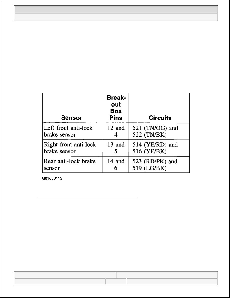
Fig. 42: Identifying Anti Lock Brake Sensor Circuits 
Courtesy of FORD MOTOR CO. 

1. Monitor the resistance between EEC-IV 60-Pin Breakout Box pins and ground as follows:  

2. Drive over rough roads at various speeds.  

3. If there is continuity between either circuit and ground, repair the circuit for a short to ground.  

4. Check harness for open circuit. 

1. Connect a jumper between the two pins on the suspect sensor connector. 

NOTE:

Use 88 Digital Multimeter with the minimum resistance hold feature 
enabled for this test.

NOTE:

Connect jumper securely to the suspect sensor connector.

NOTE:

Use 88 Digital Multimeter with the maximum resistance hold feature 
enabled for this test.


2003 Ford Pickup F150 

2003 BRAKES Anti-Lock Control - 4-Wheel - F150 Pickup


Fig. 43: Identifying Anti Lock Brake Sensor Circuits 
Courtesy of FORD MOTOR CO. 

2. Monitor the resistance between EEC-IV 60-Pin Breakout Box pins as follows:  

3. Drive over rough roads at various speeds.  

4. If there is open circuit detected between pins, repair the circuit(s) for an open circuit.  

5. Check suspect sensor electrical connector. 

NOTE:

Use 88 Digital Multimeter with the maximum resistance hold feature 
enabled for this test.


2003 Ford Pickup F150 

2003 BRAKES Anti-Lock Control - 4-Wheel - F150 Pickup


Fig. 44: Sensor Resistance Specifications 
Courtesy of FORD MOTOR CO. 

1. Monitor the resistance between suspect anti-lock brake sensor terminals while wiggling the 

electrical connector:  

2. If the resistance is above specifications, install a new anti-lock brake sensor. 

Fig. 45: Sensor Resistance Specifications (1 Of 2) 
Courtesy of FORD MOTOR CO.

NOTE:

Use 88 Digital Multimeter with the minimum resistance hold feature 
enabled for this test.


2003 Ford Pickup F150 

2003 BRAKES Anti-Lock Control - 4-Wheel - F150 Pickup


Fig. 46: Sensor Resistance Specifications (2 Of 2) 
Courtesy of FORD MOTOR CO. 

3. Monitor the resistance between suspect anti-lock brake sensor pins (component side) while 

wiggling the electrical connector:  

4. If the resistance is below specifications, install a new anti-lock brake sensor.  

REMOVAL & INSTALLATION 

HYDRAULIC CONTROL UNIT (HCU) 

Removal & Installation 

1. Disconnect the battery negative cable. For additional information, refer to BATTERY, MOUNTING 

AND CABLES - F150 PICKUP .  

2. Disconnect the anti-lock brake control module electrical connector. 

CAUTION: Electronic modules are sensitive to static electrical charges. If 

exposed to these charges, damage may result.


2003 Ford Pickup F150 

2003 BRAKES Anti-Lock Control - 4-Wheel - F150 Pickup


Content   ..  353  354  355  356   ..