Ford F150 Pickup. Instruction - part 1585


  Index      Ford     Ford F150 Pickup - service and repair instruction 2003 year


Search            copyright infringement  


Content   ..  1583  1584  1585  1586   ..


Ford F150 Pickup. Instruction - part 1585


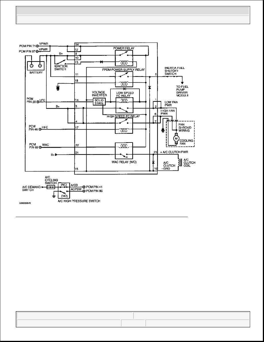
Fig. 373: Identifying Constant Control Relay Module Circuits (Mustang 4.6L) 
Courtesy of FORD MOTOR CO. 


2003 Ford Pickup F150 

2003 ENGINE PERFORMANCE Self-Diagnostics - CNG, Flex-Fuel & Gasoline


Fig. 374: Identifying Constant Control Relay Module Circuits (ZX2) 
Courtesy of FORD MOTOR CO. 


2003 Ford Pickup F150 

2003 ENGINE PERFORMANCE Self-Diagnostics - CNG, Flex-Fuel & Gasoline


Fig. 375: Identifying Constant Control Relay Module Connector Terminals 
Courtesy of FORD MOTOR CO. 

CCRM LOCATIONS 

Testing 

Application

Location

Mustang

Mounted On Bracket, Behind Engine Coolant Reservoir

ZX2

In Left Front Of Engine Compartment


2003 Ford Pickup F150 

2003 ENGINE PERFORMANCE Self-Diagnostics - CNG, Flex-Fuel & Gasoline


1) Check For Open VPWR Circuit Between IAC Valve & CCRM 
Turn ignition switch to OFF position. Disconnect fuel injector and CCRM connectors. See CCRM 
LOCATIONS
 table. Disconnect scan tool from Data Link Connector (DLC). Using a DVOM, measure 
resistance of VPWR circuit between fuel injector harness connector and CCRM harness connector 
terminals No. 12 and 24. See Fig. 372-Fig. 375 . If both resistances are less than 5 ohms, reconnect fuel 
injector and go to next step. If both resistances are 5 ohms or more, repair open in VPWR circuit between 
CCRM and splice to fuel injector. See WIRING DIAGRAMS

2) Check B+ Voltage & IGN START/RUN Voltage To CCRM 
 
Using a DVOM, measure voltage between negative battery terminal and B+ circuit at CCRM harness 
connector terminals No. 8 and 10. Note voltage. Turn ignition switch to ON position. Using a DVOM, 
measure voltage between negative battery terminal and IGN START/RUN circuit at CCRM harness 
connector terminal No. 13. If all voltages are more than 10.5 volts, go to next step. If any voltage 
measurement is 10.5 volts or less, check related fuses. If fuse is blown, check for short to ground in B+ or 
IGN START/RUN circuit. Repair as necessary and replace fuse. If fuses are okay, repair open in B+ or 
IGN START/RUN circuit. 

3) Check CCRM GND Circuit 
 
Turn ignition switch to OFF position. Leave CCRM disconnected. Using a DVOM, measure voltage 
between terminals No. 8 (VPWR) and No. 15 (GND) at CCRM harness connector. If voltage is more than 
10.5 volts, replace CCRM. If voltage is 10.5 volts or less, repair open in GND circuit to CCRM. 

15) For KOEO & KOER Only DTC P0481 & P1479: Check HFC Control Relay & HFC Circuit In 
CCRM 
DTC P0481 or P1479 is set when PCM detects a High Speed Fan Control (HFC) primary circuit failure. 
Possible causes are: 

z

Open Or Shorted HFC Circuit  

z

Open VPWR Circuit To HFC Relay  

z

Faulty CCRM (HFC Relay Or Internal Circuit)  

z

Faulty Powertrain Control Module (PCM)  

Turn ignition switch to OFF position. Disconnect CCRM connector. See CCRM LOCATIONS table. 
Using a DVOM, measure HFC relay coil resistance between CCRM terminals No. 17 (HFC) and No. 24 
(VPWR). See Fig. 375. Resistance should be 65-110 ohms. Also, measure CCRM internal resistance 
between terminal No. 17 and terminals No. 1-11, 13 and 21, and CCRM case. Measure resistance of 

NOTE:

Diagnostic procedures beginning with step 1) are performed when 
directed here from TEST C, step 5), or TEST HX, step 76).

NOTE:

A break in step numbering sequence occurs at this point. Procedure skips 
from step 3) to step 15). No test procedures have been omitted.

NOTE:

On single speed cooling fan applications, ignore DTC P1479.


2003 Ford Pickup F150 

2003 ENGINE PERFORMANCE Self-Diagnostics - CNG, Flex-Fuel & Gasoline


Content   ..  1583  1584  1585  1586   ..